I have just realised that the thin grey line is not the one you are trying to control. What is it?
The black wire is the wort which I’m trying to control. Right now it’s 5 gallons of water for test.
The grey wire is the air temperature inside my freezer.
The red wire is the heat relay which is just the output of the PID.
The blue wire is the same for cooler.
As you can see the black wire has a little noise in it even with smoothing set to 3. I think that is what is causing the majority of the indecision in the PID.
Charles
Expand the temperature scale so we can see properly what the process is doing. Not sure what you mean by indecision in the pid.
By indecision I mean that when the DS18B20 gets close to a transition in temperature it fluctuates back and forth for up to 10 minutes. That accounts for the little spikes in the black wire(wort temp). I think it may be causing some confusion in the PID because the cool and heat power seems to fluctuate along with it.

Is this what you mean by expand temp scale?
Charles
Sorry, that’s worse. 
I’ll try again.

I really meant do something like changing the temp scale to something like 50 to 70 so it would be easier to see the waveform, but that is probably good enough.
Don’t worry about the noise on the power that is of no consequence. It is inevitable when you have a sensor that goes in increments of the size of a DS18B20. It can become an issue when derivative is being used as that amplifies the noise. The Smoothing Factor in the PID algorithm helps with this but it only applies to derivative so doesn’t make any difference if the Derivative Time is zero.
It seems from your graph that in fact the process is not stable, you can see it cycling with a period of a couple of hours. I think this is likely due to an imbalance between the heating and cooling. It may well be stable when just heating but unstable in cooling. It could be that this is why, earlier, you thought you had a stable system with Integral set to 5 mins then suddenly it went completely unstable. It may be that it went unstable when cooling was called for and this pushed it into a completely unstable situation. Tuning heat/cool loops can be particularly tricky.
Can you tell me a bit more about the mechanics of the system? If I understand correctly it is a bucket in a freezer box. So the cooling is presumably just via the walls of the box radiating and conducting into the bucket. Is it a compressor type freezer with a motor? What is the heating arrangement? Is it an electrical heating element in the liquid or on the outside of the bucket or what? Is it a metal bucket? I have some suggestions that might make the loop easier to control, but need to know more detail first.
Hi Colin!
I have a Raspberry Pi3 hooked up to a box I built containing 4 40amp SSRs.

I have 3 DS18B20 temperature sensors encased in a water proof metal package.

Ambient is a DS18B20 which is simply dangling from the shelf and measures the garage temperature. Purely information. Not used for anything else.
My freezer is a 7cuft chest which is a a motor/compressor type.

Inside I have two DS18B20s; one for wort temperature and the other for the air temperature inside the freezer.
The fan is a computer enclosure fan with a 3d printed mount for the DS18B20. I did some tests early on to see how long it took from the start of the freezer to the time the air temperature changed. It took such a long time I had to install the fan to circulate the air. That reduced the lag time to about 20 seconds.
The probe in the bucket is shielded by a stainless steel tube which reaches about 14" into the bucket. The bucket, in the picture, is a 6.5 gallon fermenting bucket about 12" diameter and 22" high.
As you can see I have a lot of lag time (inertia) built into my system but it a necessary evil, in my opinion.
The PID controller works solely off the bucket probe.
Some time in the future I thought I might try to modify Kp and maybe Ki based on the difference in garage temperature and bucket temperature but that is looking more and more remote. I'm learning that I don't know as much about PID as I thought I did.
The extra wires you see are for a second freezer I use to age wine in. It holds about 55F fairly well using the IBM PID controller. I have about 40 bottles of wine in it so I can't risk experimenting with it.
Charles
Lots of good information. You haven’t said what the heater is. Is it heating the air in the box or heating the bucket?
The heat lamp in the right side of the freezer is for heating the air in the freezer.
So the fan blows air on both the cold and hot parts of the freezer.
I might add that fast changes in temperature are not good for yeast. The yeasts I have researched recommend no more than a 5F change in temp per day. That rate of change does get used at times. The lager yeast I use for my Corona Extra requires a drop in temperature from 62F to 32F for lagering.
OK, so you are heating/cooling the air in the freezer and that heats/cools the bucket.
Because the heater and cooler have very different response times and, probably, power you have to initially tune the loop separately for heat and cool and then combine them using the parameters in the heat/cool splitter node. The cooler will be the more difficult one to control so I would start with that. For the moment completely disconnect the splitter node and wire the pid node direct to the cooler time proportion node. To tune the cooling loop it will need to be in a state that requires cooling. If the weather is hot enough so that is the case then fine, otherwise connect an inject node to the heater timeprop node and configure it to feed a small value in so the heater will be on with a fixed power in order that the cooler will be required, maybe feed in 0.1 or something, whatever is required just to elevate the temperature a bit. Then let the brew warm up to a stable level above the setpoint (maybe 10 degrees) with the cooler switched off and then start the cooler and run through the startup overshoot technique as described in the tuning blog [1] to get the P and I values appropriate for cooling.
Once that is done then do the same the other way round to tune the heat loop. If the ambient is not too warm then likely you won’t need the cooler on but if it is too warm to need heat then you will have to set it to provide a bit of cooling all the time as you did with the heater above. Once you have values for heat and cool P and I then come back and we can work out what to set the actual loop to and how to configure the splitter node (which will allow for the differing P requirements for heat and cool.
[1] http://blog.clanlaw.org.uk/2018/01/09/PID-tuning-with-node-red-contrib-pid.html
Ok. Heat won’t be a problem. It’s getting up to 97F all this week here and my garage gets above 80F each day. 
Charles
Hi Colin:
I am ready to start finding my process parameters and set my Kp to 0. It’s not working because with 0 proportional band the output of the PID is -infinity%. I tried tweeking other parameters but nothing works. With Kp of 0.1 output is -30,
Here are my initial settings:
pb = 0
it = 9999
d = 0
ii = 0.5
msi = 600
dsf = 3
Can you see what I’m doing wrong?
Charles
On a point of order it isn’t Kp and Ki, that would only be the correct names for the PID algorithm that uses the more mathematical formula. For this one the gain is set by a proportional band which is in process units and integral and derviative settings that are in seconds, so it is PB, Ti and Td.
If the PID node is sending out anything outside the range 0 to 1 then you have found a bug, and looking at the code I can’t see how it could happen. Are you sure you are getting negative values, let alone -infinity?
However one of the things I keep meaning to get round to is adding a proper on/off control with hysteresis but in the meantime set the PB to a bit more than the noise level from the sensor and you should be good to go. We have already seen that it is very stable with less than one bit noise, where a bit is 0.0625 C so I suggest setting it to a bit less than 0.125C which is about 0.225 in strange foreign units I think. So 0.2F should be ok.


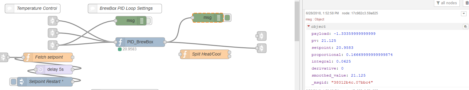
Changed PropBand to 0.125 and here's what I'm getting now.
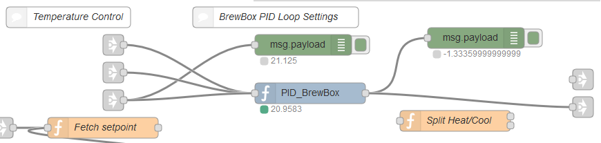
???
Can you set change the debug node to show the complete message and paste the result please. Then set the Integral time non-zero and see what happens. Zero is not a valid value but it still shouldn’t do that. I will see if I can replicate the issue.
Which version of the PID node is it?
[Edit] I see you have tried with non-zero pb and it is still -1.3. Can you post the whole message debug please.