# Relays for dummies
**URL:** https://discourse.nodered.org/t/relays-for-dummies/13714
**Category:** Hardware
**Created:** [26 July 2019 11:11 UTC](https://discourse.nodered.org/t/relays-for-dummies/13714 "2019-07-26T11:11:13Z")
**Posts on this page:** 6
**Page:** 4
### Author:  [@Paul-Reed](https://discourse.nodered.org/u/Paul-Reed)
#### Post date: [27 August 2019 21:04 UTC](https://discourse.nodered.org/t/relays-for-dummies/13714/61 "2019-08-27T21:04:37Z")
> [@iungo](#):
>
> For MRI-24D48 it's not correct schematic.
> For open signalization you need to connect A1 to PIN3(+24V), A2 to pin FCA(PIN5).
> For close signalization you need to connect A1 to PIN3(+24V), A2 to pin FCC(PIN6).
Yes I agree that this would be the best solution, as it would not interfere with the way that the door controller currently works. Good call.
> [@iungo](#):
>
> Also, as I see in the manual by your link, the OPEN button grounding PIN10 of your door controller, but MRI-3.3D48 is a positive voltage interrupter. I think you will need an additional relay for your system.
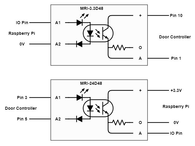
Pin 10 is normally pulled high by a pull-up in the door controller, but if it is momentarily pulled low (by grounding it with a push button), the falling edge triggers the device logic to 'open the door if it is closed' OR 'close the door if it is open'.
See [post #1 in this thread](https://discourse.nodered.org/t/relays-for-dummies/13714).
So having PIN 10 connected to the collector of the MRI-3.3D48 will enable it to be pulled low through the emitter to PIN1 (ground), when the MRI-3.3D48 is saturated.
Node-RED will be programmed to energise the MRI-3.3D48 for a set time - 100ms?? just enough to trigger the falling edge.
Why do you think that this would not work?
I have asked @BartButenaers to measure the current flow through pins 10 & 1, to ensure that it does not exceed the 100mA permitted (I would think that it would be OK and much lower that 100mA).
---
### Author:  [@markost](https://discourse.nodered.org/u/markost)
#### Post date: [27 August 2019 21:52 UTC](https://discourse.nodered.org/t/relays-for-dummies/13714/62 "2019-08-27T21:52:05Z")
For open/close state (plus optional serial resistor):

---
### Author:  [@Paul-Reed](https://discourse.nodered.org/u/Paul-Reed)
#### Post date: [27 August 2019 22:34 UTC](https://discourse.nodered.org/t/relays-for-dummies/13714/63 "2019-08-27T22:34:01Z")
@markost
Your first amendment - using pins 5 & 2, [was what I suggested above](https://discourse.nodered.org/t/relays-for-dummies/13714/56). But having thought in more detail since I posted, I can see that it may indicate a false status because of the current flow between Pin 5 & Pin 2, sending Pin 5 low.
@iungo's solution does not have that issue, and is a better solution IMO.
Your second amendment... is pretty much what @iungo has suggested, as both pins 5 & 6 are identical in operation.
The outputs on both of your amendments would work OK, I guess it comes down to personal preference.
---
### Author:  [@iungo](https://discourse.nodered.org/u/iungo)
#### Post date: [28 August 2019 05:35 UTC](https://discourse.nodered.org/t/relays-for-dummies/13714/64 "2019-08-28T05:35:55Z")
Dear Paul and Bart,
I can explain, why I recommend using NO relay in parallel to "open" button.
When I'm working on any project I always try to follow the next principle:
Reliability is more important than functionality.
I think a relay is the most reliable solution. NO relay has open default state. And if raspberry pi power will disappear it stay open.
So I recommend using MRI-3.3D48 to control NO relay.
Paul, remember, some raspberry GPIOs has a Pull-Up on boot. It is no way to configure it. Aware those GPIOs.
You can find the info about GPIOs onboot state here:
[https://elinux.org/RPi\_BCM2835\_GPIOs](https://elinux.org/RPi_BCM2835_GPIOs)
> [@BartButenaers](#):
>
> Have told my wife that I have mobilized half of the planet for my garage project
Like Qay Yuli Sezar)
---
### Author:  [@Paul-Reed](https://discourse.nodered.org/u/Paul-Reed)
#### Post date: [28 August 2019 08:25 UTC](https://discourse.nodered.org/t/relays-for-dummies/13714/65 "2019-08-28T08:25:27Z")
> [@iungo](#):
>
> I think a relay is the most reliable solution. NO relay has open default state. And if raspberry pi power will disappear it stay open.
But the opto-isolator is also NO as default, just the same as a NO relay. Unless an energising voltage is applied to Pin A1, it will remain in it's default state of NO, and certainly be the case if the Raspberry Pi's power should disappear.
> [@iungo](#):
>
> So I recommend using MRI-3.3D48 to control NO relay.
But that would also be the same result, because if the opto-isolator was energised, then the mechanical NO relay would then also be energised, so adding the NO relay would not give an added benefit.
Also consider what effect points-bounce from a mechanical relay would have on the door controller. Just using the opto-isolator would ensure a good clean switch from one state to another.
> [@iungo](#):
>
> Paul, remember, some raspberry GPIOs has a Pull-Up on boot. It is no way to configure it. Aware those GPIOs
Yes, thanks, I was mindful of that, but there are IO pins available that do not pull-up on boot, and those could safely be used.
---
### Author:  [@iungo](https://discourse.nodered.org/u/iungo)
#### Post date: [28 August 2019 08:32 UTC](https://discourse.nodered.org/t/relays-for-dummies/13714/66 "2019-08-28T08:32:37Z")
> [@Paul-Reed](#):
>
> Also consider what effect points-bounce from a mechanical relay would have on the door controller. Just using the opto-isolator would ensure a good clean switch from one state to another.
A think absolutely zero bounce effect. I think all door controller inputs have internal debounce circuit (or programming implementation). It can't work with the mechanical buttons w/o it.
[Previous page](https://discourse.nodered.org/t/relays-for-dummies/13714.md?page=3)