The PLC is fully wired-in in the house (previous owner) and is a very stable domotica system (Siemens Logo!). But no internet connection or possibilities to extend with wireless devices. That is why I started interfacing with a RPI a few years ago.
The is a newer Logo hardware on the market with a LAN / Modbus connection. But unfortunately not in my house and a big project to replace (you don't want to see the wiring )
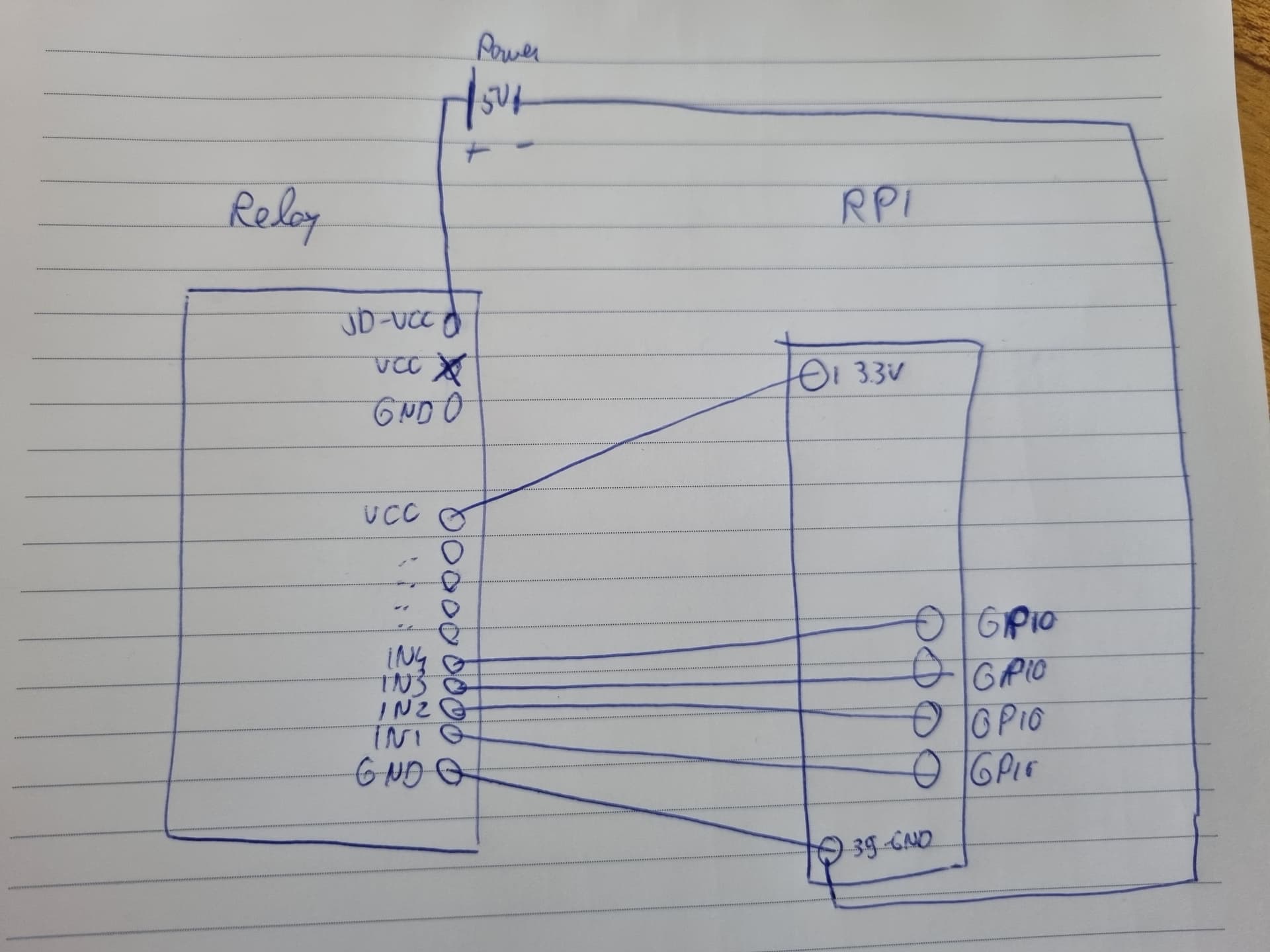
Thanks @markost , I'll try this wiring. It feels a bit strange to connect the GND of the external power supply to the GND of the RPI. But I think i've read that more often so I'll try.
The question is still whether this will fix the spike, but at least it sounds like a correcter wiring of the relays
Having considered again the circuit in the relay board (as seen in the link you posted in post 29) I realise I have to eat my words. The ground connection is, in fact redundant. The wiring you originally had is correct.
Thanks for reconsidering. The only ambiguity I still read is whether or not to connect the GND of the external power supply to the GND the relay board AND the GND of the GPIO
In the picture below the last one (GND to GPIO) is left unconnected:
And what the possible consequence is of NOT connecting the GND of the GPIO (which I have today)
In my experience, both as a Field Engineer and designer of electronic hardware for control systems, I have seen problems when the ground of a 'slave device' is not connected to the ground of 'the master'.
If they are connected, the 0V are at the same level, therefore the intended signals are at the same reference potential (as in voltage)
If they are not connected together and there is electrical 'noise' around the devices, or the lead lengths between the two are long to allow induced signal noise, things might switch unintentionally as there is the possibility that the 0-5V and the Pi voltages are floating in relation to each other and do not have the same reference.
However, the best way over this is to use isolating Opto switches where the input and output CAN operate at different levels providing the 0V of each is referenced to its own 0V. and the circuits are therefore 'Opto Isolated' from each other (especially in Medical Devices attached to Patients!!).
However, as I said earlier, I have had no problems using the 5V from the Pi to drive the relays too (an 8 relay board in my case). To do that, remove the separate supply, put the jumper back in, and connect GND on the pi to GND on the relay board.
To understand this it is necessary to understand the circuit in the relay board. The part connected to the Pi is very simple, it is just a photo diode in the opto isolator in series with an LED indicator and a current limiting resistor. The top end of the chain is connected to VCC which is to be connected to 5V on the Pi, and bottom end is connected to the control input pin, which is connected to the GPIO output on the pi. See this schematic. There is nothing in that circuit connected to the GND of the relay board, so there is nothing to be gained by connecting the GND signals together.
Just one question for the mentioned setup (+5V on top side of optocoupler, instead of +3.3V):
when the RPi gpio is in HIGH state, we have +3.3V at the input of the optocoupler.
On the other side of the optocoupler we have +5V. So, the potential difference is 1.7V and correct polarity...
Is this enough voltage to activate the optocoupler?
I would still connect +3.3V to the Vcc relay...
The optocoupler does not care about any voltage difference on both sides. As long as you have enough voltage to trigger the LED on input side, it will trigger the phototransistor on the output side. Electronically both sides are completely decoupled.
The LED and the opto coupler are forward biased silicon diodes so need a minimum of 1.4V to start passing current. If you look at the spec of the opto couplers they typically need significantly more than that to pass anything, never mind enough to turn on properly, so no, 3.3v is not low enough to drive the relay.
If you use 3.3V then you have the opposite problem. The top of the diodes is at 3.3V so the bottom will be no greater than 1.9V. When the GPIO pulls down it does not pull down to 0, I can't immediately find the spec but it is probably about 0.7V again. So when it pulls down there is less that 1.2V across the resistor on the relay board even before the opto diode starts conducting, so with 3.3V it is marginal whether the relays will pull in at all because there is not enough drive on the opto isolator.
I still think that it is more correct to use the value 3.3V, i.e. the voltage of the GPIO, to power the opto diode (both sides!),and not to mix 5 and 3.3V.
Opto-coupler power suppy; resistor top side
3.3V
5.0V
Raspberry GPIO state
LOW (0V)
HIGH(3.3V)
LOW (0V)
HIGH(3.3V)
Voltage between resistor top side and opto diode catode
Look at a datasheet for a typical opto coupler such as this one and it says it shows a typical forward voltage of 1.2V to turn it on. The LED will need 0.7V and there will be a drop across the resistor too. Therefore there needs to be at least 1.9V plus what is across the resistor. Also the GPIO output does not pull right down to 0V. Put those into your table and you will see why turning On will be marginal on 3.3V and will fully turn off at 5V.
You are absolutely right about the total voltage on the opto+LED!
I was missing the LED because I have a module that doesn't have a series connected LED (a red board with an optional jumpered H/L trigger)...
I always connect the opto side to the GPIO voltage and the relay side to the relay voltage.
With a 5V relay board, the thing will work, but with 9,12 or 24V, it won't...
Also, if you have one without an LED and connect the relay board to 5V it might blow up the GPIO input as there would be more than 3.3V on the pin when it is high.