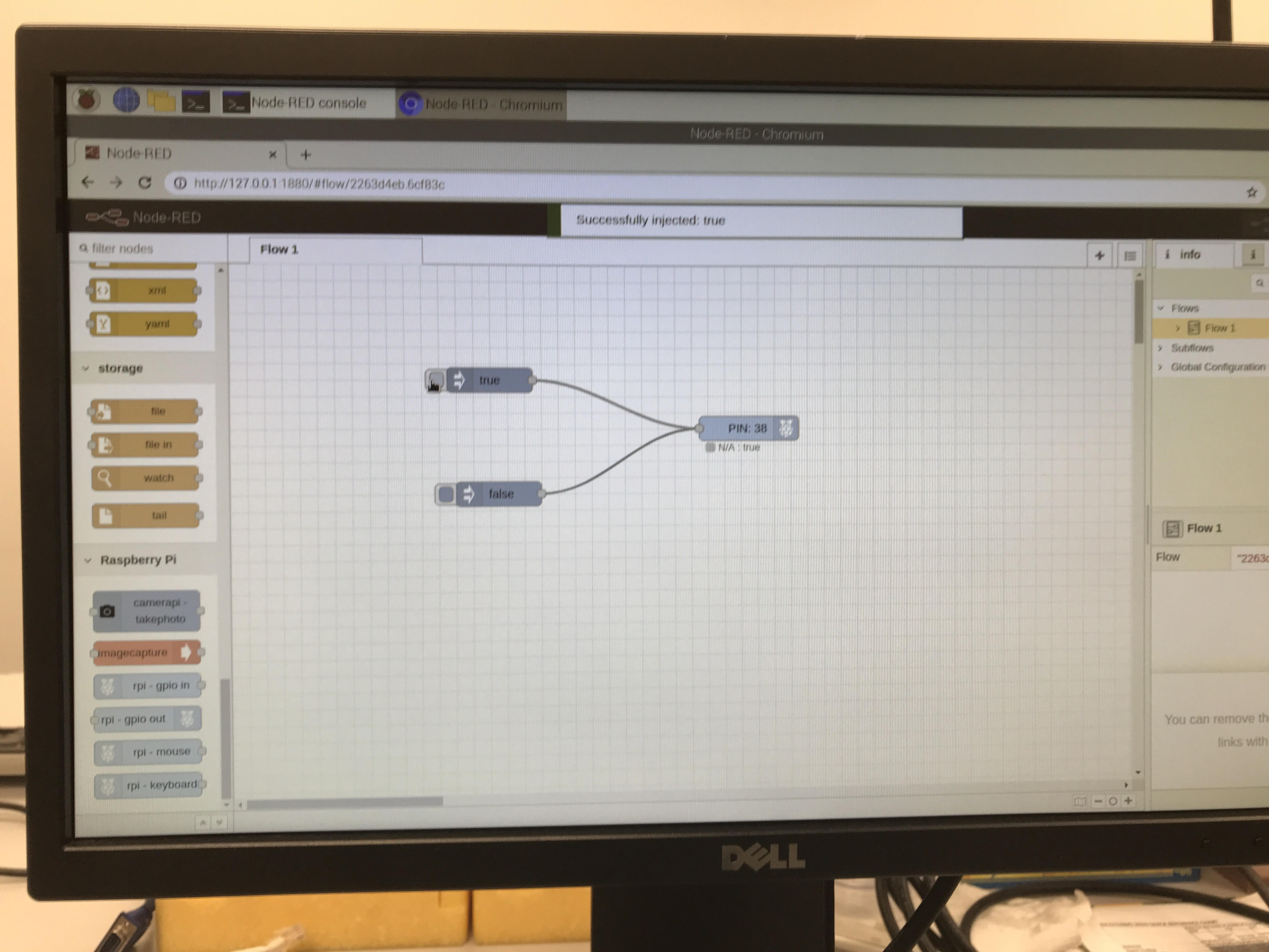
I have this experiment... No MQTT for it yet, but is shows the image in the workspace and on dashboard. Button will only let you press it once every 10 seconds (it can take about 5 to show the image), and I have a Pan and Tilt setup with my camera, but it uses the PCA9685 i2c expander for stable hardware based PWM... I left those nodes in, in case you might want to experiment with that adapter and servos as well, but they can simply be deleted if not needed.
You will have to install any missing nodes.
[{"id":"43e3cfc0.306c3","type":"tab","label":"Raspi Cam Dashboard","disabled":false,"info":""},{"id":"93aaa19c.0ef06","type":"inject","z":"43e3cfc0.306c3","name":"","props":[{"p":"payload"},{"p":"topic","vt":"str"}],"repeat":"","crontab":"","once":false,"onceDelay":"","topic":"","payload":"","payloadType":"str","x":110,"y":80,"wires":[["72a38d28.e63e04"]]},{"id":"72a38d28.e63e04","type":"exec","z":"43e3cfc0.306c3","command":"raspistill","addpay":"","append":"-w 640 -h 480 -o -","useSpawn":"false","timer":"","oldrc":false,"name":"","x":200,"y":160,"wires":[["ffb21a3d.76da08","dae5e474.b69b58"],[],[]]},{"id":"ffb21a3d.76da08","type":"base64","z":"43e3cfc0.306c3","name":"","action":"str","property":"payload","x":280,"y":80,"wires":[["d408ccb2.5e315"]]},{"id":"d408ccb2.5e315","type":"template","z":"43e3cfc0.306c3","name":"","field":"payload","fieldType":"msg","format":"handlebars","syntax":"mustache","template":"<img width=\"320px\" height=\"240px\" src=\"data:image/jpg;base64,{{{payload}}}\">","output":"str","x":440,"y":80,"wires":[["34a5983f.0a1118"]]},{"id":"34a5983f.0a1118","type":"ui_template","z":"43e3cfc0.306c3","group":"eb23a053.4aa63","name":"Snapshot Template","order":1,"width":"7","height":"5","format":"<div ng-bind-html=\"msg.payload\"></div>\n<style>\n body.nr-dashboard-theme md-content md-card {\n border-radious: 20px;\n}\n.nr-dashboard-theme ui-card-panel {\n border-radius: 20px;\n}\n</style>","storeOutMessages":true,"fwdInMessages":true,"resendOnRefresh":true,"templateScope":"local","x":630,"y":80,"wires":[[]]},{"id":"dae5e474.b69b58","type":"imageSimple","z":"43e3cfc0.306c3","imageData":"payload","imageType":"msg","autoresize":true,"original":false,"localfile":false,"flipX":false,"flipY":false,"width":"320","height":"480","rotate":0,"crop":true,"cropX":0,"cropY":0,"cropWidth":200,"cropHeight":200,"x":510,"y":140,"wires":[[]]},{"id":"ca3a98d1.adf308","type":"ui_slider","z":"43e3cfc0.306c3","name":"","label":"Pan","tooltip":"","group":"2b5eec28.269ea4","order":1,"width":0,"height":0,"passthru":true,"outs":"end","topic":"topic","topicType":"msg","min":"900","max":"2100","step":"10","x":110,"y":380,"wires":[["7509378f.2c9198"]]},{"id":"7509378f.2c9198","type":"PCA9685 out","z":"43e3cfc0.306c3","name":"PWM Output 0 (Pan Servo)","pca9685":"6ce45bce.cdff94","channel":"0","payload":"","unit":"microseconds","onStep":"0","x":320,"y":380,"wires":[]},{"id":"1a94fb4c.338225","type":"ui_slider","z":"43e3cfc0.306c3","name":"","label":"Tilt","tooltip":"","group":"2b5eec28.269ea4","order":1,"width":0,"height":0,"passthru":true,"outs":"end","topic":"topic","topicType":"msg","min":"900","max":"2100","step":"10","x":110,"y":420,"wires":[["95f4e1f5.3c411"]]},{"id":"95f4e1f5.3c411","type":"PCA9685 out","z":"43e3cfc0.306c3","name":"PWM Output 1 (Tilt Servo)","pca9685":"6ce45bce.cdff94","channel":"1","payload":"","unit":"microseconds","onStep":"0","x":320,"y":420,"wires":[]},{"id":"81d5fa20.7db83","type":"ui_button","z":"43e3cfc0.306c3","name":"","group":"d3d5aef6.5754d","order":6,"width":0,"height":0,"passthru":false,"label":"CLICK ME","tooltip":"","color":"","bgcolor":"","icon":"","payload":"1","payloadType":"num","topic":"topic","topicType":"msg","x":130,"y":280,"wires":[["7245af5f.dbbb08"]]},{"id":"7245af5f.dbbb08","type":"trigger","z":"43e3cfc0.306c3","name":"Trigger delay","op1":"","op2":"","op1type":"pay","op2type":"str","duration":"10","extend":false,"overrideDelay":false,"units":"s","reset":"","bytopic":"all","topic":"topic","outputs":2,"x":330,"y":280,"wires":[["2c2b4174.0aa20e","72a38d28.e63e04"],["fc0c5794.cd3948"]]},{"id":"2c2b4174.0aa20e","type":"change","z":"43e3cfc0.306c3","name":"msg.enabled FALSE","rules":[{"t":"set","p":"enabled","pt":"msg","to":"false","tot":"bool"}],"action":"","property":"","from":"","to":"","reg":false,"x":160,"y":240,"wires":[["81d5fa20.7db83"]]},{"id":"fc0c5794.cd3948","type":"change","z":"43e3cfc0.306c3","name":"msg.enabled TRUE","rules":[{"t":"set","p":"enabled","pt":"msg","to":"true","tot":"bool"}],"action":"","property":"","from":"","to":"","reg":false,"x":150,"y":320,"wires":[["81d5fa20.7db83"]]},{"id":"4ec50c05.eedd24","type":"comment","z":"43e3cfc0.306c3","name":"Snap a RPiCam picture for display- with P&T","info":"","x":210,"y":20,"wires":[]},{"id":"eb23a053.4aa63","type":"ui_group","name":"Snapshot","tab":"75252f1b.e6fdd","order":2,"disp":true,"width":"7","collapse":false},{"id":"2b5eec28.269ea4","type":"ui_group","name":"P&T","tab":"75252f1b.e6fdd","order":3,"disp":true,"width":"6","collapse":false},{"id":"6ce45bce.cdff94","type":"PCA9685","deviceNumber":"1","address":"64","frequency":"50"},{"id":"d3d5aef6.5754d","type":"ui_group","name":"Trigger","tab":"75252f1b.e6fdd","order":1,"disp":true,"width":"6","collapse":false},{"id":"75252f1b.e6fdd","type":"ui_tab","name":"Raspi Cam","icon":"dashboard","order":4,"disabled":false,"hidden":false}]