Yes I agree that this would be the best solution, as it would not interfere with the way that the door controller currently works. Good call.
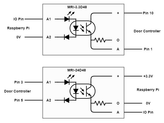
Pin 10 is normally pulled high by a pull-up in the door controller, but if it is momentarily pulled low (by grounding it with a push button), the falling edge triggers the device logic to 'open the door if it is closed' OR 'close the door if it is open'.
See post #1 in this thread.
So having PIN 10 connected to the collector of the MRI-3.3D48 will enable it to be pulled low through the emitter to PIN1 (ground), when the MRI-3.3D48 is saturated.
Node-RED will be programmed to energise the MRI-3.3D48 for a set time - 100ms?? just enough to trigger the falling edge.
Why do you think that this would not work?
I have asked @BartButenaers to measure the current flow through pins 10 & 1, to ensure that it does not exceed the 100mA permitted (I would think that it would be OK and much lower that 100mA).
@markost
Your first amendment - using pins 5 & 2, was what I suggested above. But having thought in more detail since I posted, I can see that it may indicate a false status because of the current flow between Pin 5 & Pin 2, sending Pin 5 low. @iungo's solution does not have that issue, and is a better solution IMO.
Your second amendment... is pretty much what @iungo has suggested, as both pins 5 & 6 are identical in operation.
The outputs on both of your amendments would work OK, I guess it comes down to personal preference.
I can explain, why I recommend using NO relay in parallel to "open" button.
When I'm working on any project I always try to follow the next principle:
Reliability is more important than functionality.
I think a relay is the most reliable solution. NO relay has open default state. And if raspberry pi power will disappear it stay open.
So I recommend using MRI-3.3D48 to control NO relay.
Paul, remember, some raspberry GPIOs has a Pull-Up on boot. It is no way to configure it. Aware those GPIOs.
You can find the info about GPIOs onboot state here: https://elinux.org/RPi_BCM2835_GPIOs
But the opto-isolator is also NO as default, just the same as a NO relay. Unless an energising voltage is applied to Pin A1, it will remain in it's default state of NO, and certainly be the case if the Raspberry Pi's power should disappear.
But that would also be the same result, because if the opto-isolator was energised, then the mechanical NO relay would then also be energised, so adding the NO relay would not give an added benefit.
Also consider what effect points-bounce from a mechanical relay would have on the door controller. Just using the opto-isolator would ensure a good clean switch from one state to another.
Yes, thanks, I was mindful of that, but there are IO pins available that do not pull-up on boot, and those could safely be used.
A think absolutely zero bounce effect. I think all door controller inputs have internal debounce circuit (or programming implementation). It can't work with the mechanical buttons w/o it.