Sorry, I was confused earlier, I was thinking it was the Shelley that could do that.
Note that you don't need to measure the voltage at the meter, you can have the electronics some way from the CTs and then you just have to connect it to the mains through a normal plug/socket. You have to provide power for the electronics after all, so it is no more intrusive than plugging in the electronics.
Hey Paul,
That I don't understand. You have a VT clamp, which you attach on a power wire so you can safely measure the lower voltage. So you don't need to mess with your power wires: you don't need to (dis)connect your power wires. So than it is non-intrusive, not? ![]()
Colin,
I learned here today that some devices use their power supply to measure 1 phase, and the other 2 phases are then calculated by adding 120°. If that is accurate enough, that is indeed a very simple solution.
You know that the target of my hobby is to integrate as much stuff as possible into Node-RED, and to avoid having too much outside of Node-RED. What a pitty that we cannot simply measure voltage and current with simple dumb hardware, and then integrate the calculations in one or more Node-RED nodes (like e.g. the 120° addition). That would have been very cool...
Hi @janvda,
Thanks for the extensive description!!
It is nice to see so many feedback here. So weird that after hours of googling, this device (of 83 euro) has never popped up on my screen. Will add a picture here for those that don't like to click on hyperlinks ![]()
I see that you can also plugin a simple board to have WIFI. Will need to have a closer look at the documentation during the weekend...
No, its not a VT clamp, its a AC voltage transformer that is hard wired into one phase (or 3 AC transformers for more accuracy - one for each phase).
Just looking at iotawatt website it says;

For a single phase system, iotawatt recommend this;
https://uk.farnell.com/ideal-power/77de-06-09/power-supply-ac-ac-10w-9v-0-67a/dp/2368012
...but of course it would be difficult to use a 2 pin version on a 3 phase system, as you need it to monitor 1 phase only per transformer.
I don't use, and have never seen a iotawatt, but perhaps @craigcurtin can explain how he get's around this apparent obstacle.
Hi I just added 6 PZEM-004Tv3 onto 1 WT32 ETH01 running with ESP_Easy_mega_20221105_energy_ESP32_4M316k_ETH. I am measure all data and send to my mqtt. Further processing per nodered


I can also measure herz an cosPi
I do not know up to how many PZEM-004Tv3 i can connect, because i did not figure out ho many addresses i can give to the PZEM, the ESP32 can do 32.
The power supply is looped through all the modules because the heating system is only one phase and branches out from the central unit to the modules and I wanted to know in detail what the individual consumption of each module is.
For three-phase current or different phases, each module can of course get its own supply (requires) for measurement.
I am very satisfied with this solution. The shelly 1P and 1PM did not work reliably (something in the powerline reset the things, rebooted and shot them up), I needed an extrea AP to have sufficient reception there. Now everything is in a box of 10x10x8 cm wit TCPIP cabel and can also be installed in the control cabinet where I have no WLAN reception at all.
EDSTOBI
Hi @edstobi,
Thanks for sharing your project!
I am a fan of the wt32-eth01 devices, so you have my attention ![]()
But after the discussion of the "non-intrusive" solutions today, I had a look at the pzem-004tv3 again.

The green terminal block seems rather fragile to me? Which is of course no problem to attach the thin wires of the CT clamp. But I am wondering if it is safe enough to attach 230V AC power wires into it?
Although this setup on youtube looks rather solid:

Do I understand correctly that you only measure the voltage on one of your pzem devices, and that all your other pzem devices only have a power clamp attached to it. Or do you have 230V AC power wires to all your devices?
Not sure if I understand your picture correctly: the green terminal blocks, are those the terminal blocks of the pzem-devices (which are installed inside the red box)?
The green terminal block seems rather fragile to me
No my original built-in were remarkably reasonable.
I have replaced the existing terminal blocks with Phonix plugs/sockets. These are designed for a nominal cross-section of 2.5 mm2 , a nominal current of 12 A and a rated voltage of 320 V (III/2).

They are touch-safe so that I can safely disconnect them during operation without having to switch off the heating system. A pure passive measurement, different from the way I worked with the shelly.
However, only a few mA go through them for operation and volt and frequency measurement. I have exchanged the blocks so that I don't have to disconnect any wiring when I need to access the box.
Instead of taking the voltage from each module of the heating system, I only use it once, as everything is the same phase and comes from the same supply. So in your schematic picture these are exactly the thin blue and red wires.
No power for the pump, fan, solar pump ....
Here is an interesting report how to pimp the PZEM and a good explanation how it works.
Modifying the Peacefair PZEM-004T AC Comms Module (with schematic)
that you can understand better than indunesian
Yep you do not hardwire the IOTAWATT it - there is a recommended external power supply to purchase for each region (as these are heavy wire based transformers and hence shipping is expensive)
It is a simple Voltage transformer that plugs into a normal power point for the country you are in (in Australia this is a normal 3 ping plug - it is completely enclosed - this is used as the voltage reference and plugs into the IOTAWATT with a 2.5mm plug
The IOTAWATT then gets its power for the ESP and other onboard electronics from a (User supplied) USB power supply.
Here is a picture of the Australian recommended one

Craig
Hi Craig, I can understand how using that VT would work for single phase installs, but not for 3 phase which we are discussing here.
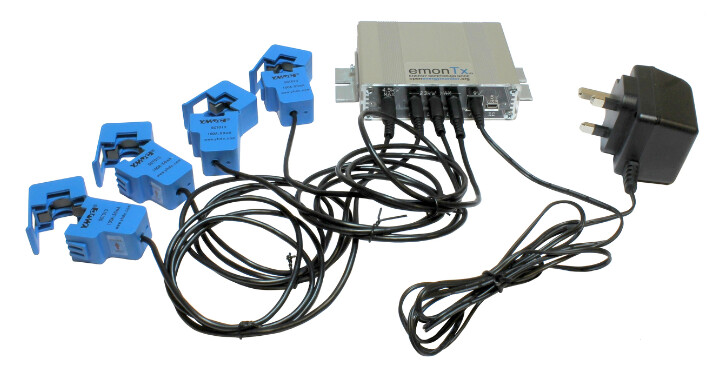
A lot of other similar systems use a single VT plugged into a socket for single phase, such as the EmonTX, but I can't see how you can obtain a reference without either using a VT wired into each of the 3 phases, or using a VT wired into just one of the phases and using that as a derived reference.
If you look at the iotawatt case, you'll see 3 VT sockets, one for each phase, one top left, and a further 2 at the bottom.

And in the iotawatt documentation it says;
To use Direct Reference three-phase power measurement, it’s necessary to install two additional VTs (total of three), and to plug each of them into a receptacle that is supplied by a unique phase
Or by using derived reference
Set up your IoTaWatt with the voltage reference VT on whatever phase of the three-phase is convenient
...and then goes onto describing how the iotawatt uses that phase to derive the other 2 phases by iotawatt shifting it by 120° or 240°.
If you want to accurately measure the power you need to measure the PF on every phase, if not you may as well just estimate the voltage, you will most probably be just as accurate if you estimate. And you cant just add 120° to each phase.
You PF is due to the phase shift between the A and V, this is due to the combined affect of the induction and capacitance on the phase. So if you want to be accurate you need to measure each phase.
Most of the time you will find that transformers and electrical motors are responsible for the phase shift, that is why a lot of factories have PF correction, they are mainly just banks of capacitors.
Pure resistive appliances, like heaters, have very small affect on PF, just about 0.
I totally agree Johan, and am of the opinion that if you are going to the expense and trouble of monitoring power, you might as well do it accurately. ![]()
You need to measure the power factor on each phase, but the phase and value of the voltage should not change. That is forced by the incoming supply and should be well controlled. It is the current that changes phase to give the PF and will be different on each phase. Therefore it is necessary to have current transformers on each phase measuring the current, but it should only be necessary to measure the volts and phase of one phase to give a reasonably accurate power reading. The volts on each will vary a little if you put a high load on one phase, due to voltage drop between you and the substation, but it should not be significant.
I am only measuring voltage of one phase. That was very easy as it is just using av available power socket inside my meter cupboard and the same is used for powering my device.
Measuring the voltage of the 2 other phases would not be that easy. I don’t have a power socket for the 2 other phases near my meter cupboard.
You are making the assumption your phase are well balanced as far as load is concerned. Do you always use your pool pump, fridge and stove at the same time?
If all you 3 phase are balance you can maybe get away with measuring only one phases PF, but it is very unlikely. Like having a single 3 phase motor connected.
You will find most probably you have you lights and stove on one phase, pool pump and fridge on the next and your wife sewing machine on the last phase, you cant compare a 100% resistive circuit to a 100% inductive circuit to your wife sewing machine ( ![]() )
)
Utilities make sure they measure each one individually, to bill you to the max and the law also forces them, as they understand the PF can differ tremendously.
Is let = var?
Like we have here in Finland ![]() .
.
It might have something to do with our cottage being almost "in the middle of nowhere" but at least I measured relatively big differences between the phase voltages (230-234V). After doing some more research, I realised the fact how inaccurate the current clamps already already are, also having "in the ballpark" Vrms could result in nearly useless accuracy. The clamps that come with Shelly 3EM are 120A rated with only 1% accuracy.
Eventually I was able to convince my electrician friend to install the Shelly 3EM in the sauna/guest room building which also has 3 phases coming in to a distribution board indoors). At this building I was most interested in how much the water pump, underfloor heating elements and incoming water pipe heating consume over time.
After monitoring the mesured numbers for the last 3 weeks of our stay extending one week onto September, the results were totally unexpected (and here the importance of accuracy comes in the picture). The biggest consumer turned out to be a phase wire powering two LIFX bulbs (mostly off) and a PoE switch with two CCTV cameras and a Raspberry Pi w/ a PoE HAT and camera. Based on the 3EM measurements, they consume a constant 22W which initially seemed insignificant compared to e.g. the water pump sucking 650W when ever a water tap is open.
My instinct told this was about JavaScript's let and var keywords. But since neither was mentioned on this thread, I assume you're referring to the unit VAR mentioned on the linked page(?):
A VAR is a unit of measurement of reactive power. VARs occur when AC electric currents and voltage are not in phase. Current and voltage become out-of-phase due to certain loads that require reactive power, or VARs.
Source: Volt-ampere reactive (VAR) · Energy KnowledgeBase.
Edit: I had never heard the term prior to listening this fascinating (even if way over my head) episode of The Amp Hour podcast: #583 – The Smart Grid with Paul Zawada | The Amp Hour Electronics Podcast. People interested in solar or renewable power in general could find this interesting as well.
No. Power Factor is a measurement of the difference between the phases of voltage and current, but it is mostly the current that changes phase, not the voltage. The assumption I am making is that the power supply to the site is good quality, with the voltage and phase of the three phases well matched. The type of load on each phase will have minimal effect on the phase of the supply voltage. Obviously separate measurement of the voltage and phase of each phase is going to be better, but if it is not practical to do that then measuring just one may be good enough.
In that case then you would have to measure all three phase voltage/phases.
The point I am trying to make, just like let and var seems like the same thing, two phase might seem the same, but they are not. LOL
Exactly and that's how the 3EM is now installed. ![]()