Hi @edstobi,
I would appreciate if you could share a bit more details about your settings, wiring diagram, ...
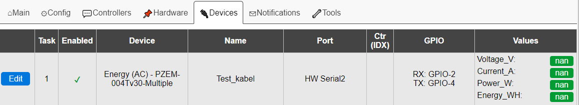
Because I have now added 1 pzem-004t module to my wt32-eth01 but I get no values. Although I have used the same settings as you:
@edstobi,
After a lot of trial and error, I learned a lot about pzem-004t but I still get NaN values.
If you are still around here on Discourse, I hope you can give me some advice...
I have a PZEM-004T connected to a Wemos D1 Mini (ESP8266) flashed with Tasmota that reports readings via MQTT to Node-RED. Here's a link to a thread about interfacing the device.
Couple of things to note are the need for level shifters and make sure Tx & Rx are connected correctly.
i.e. Tx connects to Rx, and Rx to Tx
So I have set the data acquisition interval for this device on EspEasy to 10 seconds. So every 10 seconds the RX LED on my pzem-004t is flashing, and immediately afterwards my TX LED is flashing. So I assume the pzem-004T knows correctly that he is device with address 1 and that he responds with the measurement data.
What I also not really understand: the receive LED (D3) on my pzem-004t is always on, and flashes intens when it receives a command. On the other hand the transmit LED (D2) is always off, and only flashes when it transmits the results. Not sure if that is normal behaviour of the D3 LED?
1: The circuit drawing IS correct, and I have it working here on my desk to prove it
"Not sure what they are trying to make you do there, as those diodes (what voltage let they pass through?) effectively block any signal to flow to the ESP. "
This is not true as the signal in question is flowing TO the PZEM via the diode, since the PZEM pulls the line LOW.
2: Are you still using GPIO 15 as this seems to have a pull up resistor which will have an effect on signal levels, so pick another one!
3: You will need to set the addresses on the PZEMs, I think they are all set to 1 by default.
NOTE, you can only have 1 PZEM connected at a time when setting an address, and there is no feedback, so best to make sure everything is working before trying to set the addresses.
4: The PZEM must be connected to MAINS or it will not work at all, as this powers the internal circuitry, the voltage from the EPS is only to drive the leds.
5: As a quick test you could try wiring the PZEM without any resistors diodes etc, but connect to 3.3V on ESP.
6: Based on your drawing there is 5V on the PZEM RX pin, then the other side of the diode 3.3V, since this is lower, some current can flow through the diode towards the ESP and light the LED all the time.
Ah I had added it just for completeness. But thanks for the effort!!
Oh, could you please double check if your setup is the same as my diagram above?
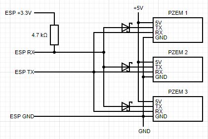
I had drawn that diagram quickly during my short lunch break today, to get some feedback.
But in my hurry it seems I have drawn it incorrectly
My setup looks currently like this:
So I would REALLY appreciate if you could double check my drawing with your setup.
I have done it like that, because in our other discussion on Discourse it was adviced to do it that way. Although now I see that in that drawing the pull-up resistor was connected to 5V while mine is connected to 3V3. Perhaps that is my issue?
A little bit further in that same Discourse discussion it was agreed that the diodes were in the wrong direction. But afterwards on the EspEasy I was adviced that I needed to turn them again. So now they are positioned like in my last drawing.
Summarized: I don't know whether my resistor needs to be attached to 3.3V or 5V. And I don't know if my diode is in the correct direction. And I also whether I could have damaged my gpio pins due to all my tampering...
Aaaah, a cable consistint out of both neutral and phase. Which probably eliminate each others reading I assume. I will create a setup tonight so I can measure only the phase...