Im trying to get a 0-5 volt pressure sensor to interface with the pi. I have the ads1115 node in node red and have it connected with no issues and it is displaying data. My issue is what its displaying. Currently it says 41.1 in the debug. Currently the sensor is not reading pressure as its not installed. So my first issue is getting it to read the correct pressure and then it read it in psi.
Just had a quick look at the datasheet for the ADS115.
It has a 16-bit ADC driven from a 4 channel analog switch.
It also states the maximum input voltage for the ADS1115 is 5V.
Just remember the pins on the pi are only 3v3 tolerant so don't be tempeted to connect anything that would input a voltage greater than this - as it would probably damage/destroy the pi.
A 16-bit ADC should have 32,768 steps. This means the maximum input voltage (e.g. 5V or 5000mV) is divided by 32,768 to give 0.153mV per step. So the integer value coming out of the device (via I2C) indicates how many increments of 0.153mV have been detected.
So in your example >> 41 means 41 lots of 0.153mV which equals 6.27mV.
Note: This output could just be noise.
I have a couple of ADS115 on order, so as soon as they arrive I'll do some tests of my own.
Hope this helps.
i did find by looking up general examples that the 41 maybe equal to 0 as a pressure reading but i havent found anything about how to read it in node red. I also found a write up where a person used python and was able to get a reading. I tried putting the code in the python node and it wont work. Heres the link.
https://www.rototron.info/raspberry-pi-analog-water-sensor-tutorial/
I don't connect any sensors to my various Raspberry Pis (I just use them as a server running Node-RED and MQTT).
Like a number of people on this forum we use ESP8266s to do the work capturing data and sending it via MQTT to Node-RED.
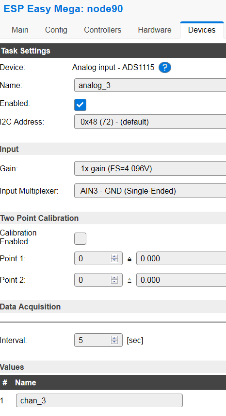
The WeMos D1 Mini is a typical device based on the ESP8266 and if you re-flash the firmware with ESP Easy then all the drivers you need for a multitude of sensors and transducers is already built-in.
https://www.letscontrolit.com/wiki/index.php/ADS1115
I'll take a look at your link later this morning.
Im also using ds18b20 sensors on the w1 bus. So id connect all my sensors through one of those boards and connect communication through i2c?
You can connect multiple i2c devices to an ESP8266. The ESP device has built-in WiFi so you would get it to talk direct to your MQTT broker. Alternatively, you could get it to talk direct to Node-RED using a TCP or UDP node but really, MQTT is a lot better.
Another alternative would be to use an Arduino with a serial connection to your Pi then use the serial-in node to get data across. That would be if you don't want to use WiFi.
Just had my set of ADS1115s delivered and lashed one of them up on a breadboard.
Here are some screenshots of the results of sampling a voltage divider consisting of two 10K resistors (in series) from +3.3V to GND. This forms a divide by 2 network. The mid-point of the resistors connects to input A3 on the ADS1115.
The reading from the ADS1115 is 13157, so if you divide this by 32,768 and multiply the result by 4.096V (as I'm using a gain setting of 1x) you get 1.645V. This is as near as 'dam it' to half +3.3V which is what the voltage divider is giving out.
I've connected A0 to GND and as you see the output is zero volts.

I already have a arduino for using a thermocouple which is sending over sensor info through the serial node. So can i add the pressure sensor to that as well and have both sensors processed by the arduino and sent over to the pi?
I do know if i set the multiplier in the node to 0 it reports 0. But im not sure if thats a true reading.
Absolutely. I recommend putting a stop character on your Arduino serial outputs - something you wouldn't normally use such as a $. This makes it easy to validate the input in Node-RED - it is possible to get missing characters off the end of a serial output.
Been a while since I've done any engineering like that but I've always validated the input so perhaps you have a known weight with which to check the sensor?
Its a water pressure sensor which ive already figured im gonna need to make something to check calibration.
OK, shouldn't be a problem - you just need a container of a known size with the sensor at the bottom ![]()
in arduino i was able to find some code and got the reading correct. Now im getting both sensors displayed in serial monitor. Now how do i separate them when they go though node red? i tried using a switch and had no luck.
I also use the Ads1115 for a Raspberry Pi project.
Common need to use voltage dividers made me create:
node-red-contrib-voltage_undivider
https://github.com/meeki007/node-red-contrib-voltage_undivider
This way I can see the voltage coming in before it hits the voltage devider.
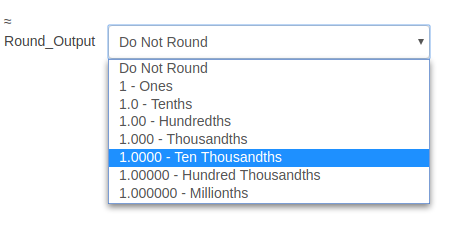
That looks useful. I am a bit confused by the comments about output rounding and number of significant digits if it is not rounded. What type are you passing on? A number or a string?
A number comes in A number goes out.
Because of conversions decimal places can get rather large. The round is to crop off excess.
I think generally it is not considered good practice to round values until the point of display, there is no point throwing away accuracy until you have to. Most UI widgets allow rounding so it can be done then
The default user option is "Do Not Round" so the user can decide if they want to round or not. Its the users choice.
It is not that so much as a philosophical point about node design, whether a node that fulfils one purpose should also perform unrelated operations.
You presumably have each connected to a separate serial-in node? If so, simply add a change node immediately after the input and set the topic accordingly. I often add a timestamp as well at that point and maybe some other metadata if needed.