Hi folks,
Had installed an electromagnetic valve for my sprinklers, which I need to control now via Node-RED. The valve contains a solenoid, and multiple options are available:
- Standard solenoid 24V AC
- Optional solenoid 24V DC
- Optional solenoid 220V AC
- Optional solenoid NO 24V DC
- Optional solenoid NO 24V AC
- Optional solenoid NO 220V AC
So I have now by default a 24VAC solenoid in the valve. But don't have a 24V AC source, only a 24V DC source. Should I buy now a 24V DC version, or is there an easy way to use the one I have now?
Thanks!!
Bart
Hi Bart,
I think a 24v DC should make that solenoid work.
Just on a side note: are you only starting this project? Do you have all the solenoids needed?
Only that I just found some great 12vDC solenoids at a steal of a price.
If you want more details, I will post the link.
I think you will need a 24v DC solenoid to be on the safe side.
It is possible to run an AC solenoid on DC, but the voltage would need to be less than the AC rating, ie less than 24v, or it would cause too much power to be dissipated in the coil.
Some examples here:
Hi Bart,
do you use Raspberry Pi as control unit ?
If yes, use a ULN2803A chip as driver for 24V valve.
The count of valves are depend on current of valve.
I can send you the circuit diagram.
Yes, they are already glued in place. But they can also be controlled manually, which I currently use as a workaround 
Ok thanks for the tip!!
Yes via a gpio port I switch an optocoupler that should provide 24V to the valve. In the link above they mention 2.2W at 24V DC, so that should not be much current...
If you are controlling multiple solenoids, you can get a 8 x open collector IC.
Then you just connect the GPIO to the IC via a nominal resistor.
The output of the IC drives a relay (I love them) to power the solenoid. Include a flyback diode on the relay.
That eliminates the need to isolate the RPI and the 12v.
I have an Arduino powering 5 of them (and pump) and it has worked for about 5 years.
Oh, this is inverting, so you have to send a 0 to activate the output.
But all in all it makes it easy to do.
The relays are optional - I use them as I grew up with them.
You could drive the solenoids directly from that chip if you want.
(Just don't forget the fly back diodes)
P = Power (W) V = Voltage (V) I = Amps (A)
P=V*I so, I = P/V
2.2W/24V just less than 0.1A (continuous)
However, there will be a surge of current drawn when the solenoid is energised. Personally (and not meant as criticism of other options!), I think the Opto Isolator is the best safest choice for isolation (airgap), but having said that, the ULN2803's are very reliable.
...and just to add confusion, you could also use a FET!!
EDIT: Good point Andrew, Flyback diodes should be added across and solenoid/coil to suppress any voltage created when the solenoid is switched off.
There will/could be problems if the 24v is powering the RasPi.
I would suggest a heap of 0.1u ceramic caps (300v) all over the place.
You WILL need high voltage caps. I forgot that and when testing some exploded.
(Fun)
There are huge back-EMF pulses either from the relay or solenoid/s.
And maybe a big diode and capacitor going to the RasPi to help isolate it from the noise at the 24 level.
Actually maybe 2 big diodes.... 1 - to the RasPi (and big cap) and
2 - to the rest of the circuit.
The second diode will stop any spikes going back to where the other diode/capacitor (powering the RasPi) and keep things separate.
Yeah, and that may be why I also included physical relays in my build.
But I am also only running at 12v.
(Arduino friendly)
Early ones had the barrel input with 12v input capability.
So the entire circuit was basically 12v design and the IC was the interface - being open collector output.
(Oh, and the IC made is a nice easy thing to use. Real estate was limited in my build)
Suggestion to the front end of the power circuit.
I guess a 7805 should work, but may need a heat sink on it.
(And the two associated capacitors)
The ULN2803A has internal flyback diodes. You must connect +24V to COM pin. The ULN2803A switches to ground if the gpio is 3.3v.
Therefore the common of all valve are connected to +24V.
Look at the Hunter latching solenoid
The -24 is a bit confusing for me.
If it is 24vDC, wouldn't it be 0v and +24v?
Sorry.
Its minus pole of 24V dc supply, names can be ground or 0V.
I wasn't trying to show you up, but it just bothered me that in my world as you showed it, that was a 48V supply.
Bart,
In the agricultural world they use 24v AC almost exclusively
- It is a fairly low voltage so not dangeourous if cut in the garden etc
- Most importantly it allows for long distance runs with little voltage drop (unlike DC) - this may or may not be an issue for you - depending on the distances involved.
Craig
Hey guys,
Thank you all for guiding me with my noob electronic question.
Would like to avoid having to install chips like ULCN2803A, and use the same optocouplers that I always use. Because those are nicely din-rail, and then my setup looks at least a bit clean to my wife
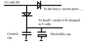
I found somewhere the below (minitiature) image that I would like to use in my experiment, in combination with the opto-couplers that I had already installed:

And then I will need to see if I need to add capacitors also.
Now I need to select the right flyback diode. If anybody has some advise about that, that would be nice. The only thing I know about the solenoid is that it uses 2,2W at 24VDC...
I only mentioned the opencollector chip as that is what I used and it is 1 chip for up to 8 solenoids.
(That diagram..... I think the solenoid is the wrong way around.) Just looking at it, if there is enough pressure the seal would be forced open..... But sorry, that's being petty.
It does convey the meaning and that is enough.
As for capacitors..... The would go from the diode's Cathode to - and be 400 volt rated.
I think they would be 0.1 micro farad ceramic caps.
400 is ... nominal. As I explained, I use 12 volts and bought 40 volt caps and a couple of them exploded when used. So I went HIGH VOLTAGE WRT INPUT.
It's because of the back EMF (the coil collapsing and creating extraneous voltages that are above the supply voltage.
While not drawn conventionally I think it is the right way round in that the flyback diode must block any forward current in normal operation.
I also think there is a trick to which side of the optocoupler you put the solenoid.
That is:
Is it + --> solenoid --> opto --> -
or + --> opto --> solenoid --> -
I think the first one is better if the opto is NPN type.
Something to do with sinking/sourcing the power.
Could someone check me on that?
