Example flow for control a motor

Hi guys,
I've started writing a guide to automating with Node-Red.
In the guide I want to show what options there are,
for solve an automation problem.

This is the task:

A motor is started with one push-button and stopped with an another push-button.
The motor has an over-temperature switch.
When this switch is closed, the engine is stopped and its prevents from starting again.
A lamp or LED indicates that the over-temperature switch is active.

The first solution is a pure hardware solution with buttons, lamps and relays:

scematic

Of course you can solve this with Raspberry Pi and Node-Red.
Here my question to you:
If you assume that the Raspberry Pi is wired as follows:

GPIO19 -> Motor OVERTEMP switch
GPIO21 -> START push-button
GPIO20 -> STOP push-button
GPIO23 -> MOTOR RELAY
GPIO24 -> MOTOR-OVERTEMP LED
GPIO25 -> MOTOR-ON LED

How does the flow look like for Node-Red?
I think that the guys in Forum will find an easy solution.
I add this solution then in my guide.

Thanks,
Ocean (Derya)

1 Like

My first comment would be don't do the overtemperature stop in node red. Do the LED in node red by all means, but the interlock should be in hardware so there is no way that a bug in the flow can burn out the motor.

1 Like

Good security aspect.
@Colin Is that OK ?

Solution with Rasberry Pi

That looks like a pretty good circuit.
You just need to sort out the NR flow in the Pi now.

Please be very careful with the MAINS wiring on the contacts of the 5V relay.

Have you considered using an opto-coupler or a solid-state-relay (SSR) to keep the mains and the logic circuitry well away from each other?

Please take care.

Here's an example of a SSR for an AC application.

1 Like

Just had a very quick go at creating a simple flow. (I'm sure it can be simplified.)


I've used 'green' for OFF and 'red' for ON. Some people prefer the colours the other way round.
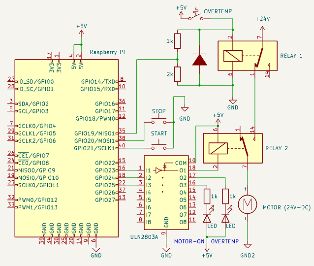
I've also set the input pins with pull-ups, so the inputs are active LOW (pin shorted to ground).
According to your diagram, the relay is operated when the output pin is LOW.

[{"id":"dcbdc7f59c771cef","type":"rpi-gpio in","z":"061e6706bc551e8f","name":"Start_button","pin":"21","intype":"up","debounce":"25","read":false,"bcm":true,"x":170,"y":360,"wires":[["6e2a412933384981"]]},{"id":"4593b98cd7e79233","type":"rpi-gpio in","z":"061e6706bc551e8f","name":"Stop button","pin":"20","intype":"up","debounce":"25","read":false,"bcm":true,"x":170,"y":260,"wires":[["eeccab846ba426c0"]]},{"id":"838f715684cd618a","type":"rpi-gpio out","z":"061e6706bc551e8f","name":"Motor_relay","pin":"23","set":"","level":"0","freq":"","out":"out","bcm":true,"x":790,"y":240,"wires":[]},{"id":"51dc944c0dab2799","type":"comment","z":"061e6706bc551e8f","name":"Assuming buttons are Active LOW","info":"","x":240,"y":100,"wires":[]},{"id":"be04b5291db74554","type":"inject","z":"061e6706bc551e8f","name":"","props":[{"p":"payload"}],"repeat":"","crontab":"","once":true,"onceDelay":0.1,"topic":"","payload":"1","payloadType":"num","x":170,"y":160,"wires":[["6a27ec01cc850822"]]},{"id":"6a27ec01cc850822","type":"change","z":"061e6706bc551e8f","name":"","rules":[{"t":"set","p":"motor_relay","pt":"flow","to":"OFF","tot":"str"}],"action":"","property":"","from":"","to":"","reg":false,"x":400,"y":160,"wires":[["7b4b5ef2c80cdb62"]]},{"id":"eeccab846ba426c0","type":"change","z":"061e6706bc551e8f","name":"","rules":[{"t":"set","p":"motor_relay","pt":"flow","to":"OFF","tot":"str"}],"action":"","property":"","from":"","to":"","reg":false,"x":400,"y":240,"wires":[["7b4b5ef2c80cdb62"]]},{"id":"6e2a412933384981","type":"change","z":"061e6706bc551e8f","name":"","rules":[{"t":"set","p":"motor_relay","pt":"flow","to":"ON","tot":"str"}],"action":"","property":"","from":"","to":"","reg":false,"x":400,"y":340,"wires":[["7b4b5ef2c80cdb62"]]},{"id":"7b4b5ef2c80cdb62","type":"function","z":"061e6706bc551e8f","name":"","func":"let relay = flow.get(\"motor_relay\") || \"OFF\";\n\nif (relay == \"OFF\") {\n    node.status({fill:\"green\",shape:\"dot\",text:\"Relay is OFF\"});\n    msg.payload = 1;\n    return msg;\n}\nelse if (relay == \"ON\") {\n    node.status({fill:\"red\",shape:\"dot\",text:\"Relay is ON\"});\n    msg.payload = 0;\n    return msg;\n}\n\nreturn null;","outputs":1,"noerr":0,"initialize":"","finalize":"","libs":[],"x":620,"y":240,"wires":[["838f715684cd618a"]]},{"id":"1fa7b0c1ebe3d5be","type":"inject","z":"061e6706bc551e8f","name":"Test Stop btn","props":[{"p":"payload"}],"repeat":"","crontab":"","once":false,"onceDelay":0.1,"topic":"","payload":"1","payloadType":"num","x":190,"y":220,"wires":[["eeccab846ba426c0"]]},{"id":"db91334e3e60c1ab","type":"inject","z":"061e6706bc551e8f","name":"Test Start btn","props":[{"p":"payload"}],"repeat":"","crontab":"","once":false,"onceDelay":0.1,"topic":"","payload":"1","payloadType":"num","x":190,"y":320,"wires":[["6e2a412933384981"]]},{"id":"f78b40a92aa3d54d","type":"comment","z":"061e6706bc551e8f","name":"Assuming relay is activated with a LOW","info":"","x":870,"y":200,"wires":[]}]
1 Like

Is the overtemp trip built into the motor? If so is it rated to drive the motor?

The thermal protection depends from motor size.
Normally one or more bimetal switch is used and mounted in motor.
Very big motors use electronic protection relay.

That doesn't answer the question, is the bimetal strip rated so the motor can be powered through it?

Yes, you can use this SSR. But you use also the uln2803 driver, because the RPi pin can't drive the SSR.
Normal relays have an insulation voltage 3-10kV between contact and coil.
I see relay boards from china, where the relay coil and input are connected common to ground. This is stupid because the surge comes over ground. The opto-coupler is in this case not working.
Did you teardown a SSR ?

No, the contact rating is very low. Therefore I use a relay switched from thermal contact.

I don't understand the above statement - can you explain it a bit more?

Hi David,

the output current of RPi is limited to 16mA per pin and total 60mA, this is the limit of the 5V/3.3V step-down converter on RPi.
Ok for one SSR is possible to connect direct to RPi pin.
But this is always a risk.You can damage the output fet on RPi.
The RPi isn't cheap and at moment not easy to get.
Therefore I use always the driver ULN2803 (cost 50Cent and easy to get).
This chip can drive 500mA per channel (2.5A total) and up to 50V voltage.
And if you use relays or valfs, the ULN2803 has builtin diodes for prevent high voltage on operate.
In the event of a surge, the ULN2803 dies and the RPi survives.
The ULN2803 can also be used as input level converter for input voltage up to 30V.

1 Like

So your statement is technically inaccurate - as a RPi can drive a SSR.

I've looked at the circuit that appears in the YouTube video and estimate the current flowing through the optocoupler, when it is connected to a 3V3 supply, is 1.6mA - well within the capability of a RPi.

I agree with you about the RPi being an expensive and hard-to-get item, and because of this fact
I never let my IoT students connect anything directly to a GPIO pin.

If I was building this circuit I'd probably substitute a Power MOSFET like a 2N7000 for the ULN2803A (as in your circuit you are only using one section of the octal driver). This would save on PCB real-estate as the ULN2803A normally comes in a DIP18 package (a lot bigger than a T0-92 encapsulation).

At the start of this thread you said you are writing a guide to automating with Node-RED.
So in your guide you could say something like.. "Although the RPi is capable of driving a SSR it should be borne in mind that this is an expensive item and can easily be damaged. A safer solution is to use an inexpensive component like an ULN2803A or a Power MOSFET to do the interfacing."

Just my two-pennies worth.

2 Likes

Thank you for your answers.
You're right, a 2N2007, a resistor and a diode take up less space and
200mA current from the 2N2007 is not small.
But with 8 x 2N2007 it gets bigger.
I took the ULN2803 because it was already in a different circuit diagram. (Copy/Paste :slight_smile: ).

My comments, about using a 2N7000, were based on the diagram you posted.

OK, in that case then yes, you need a relay or SSR for the protection circuit.

I am not sure what surge you mean, can you explain?

If you have a separate ground for the coil do you mean you have two isolated power supplies? One for the Pi and one for the coil?

I would like to show in the tutorial how the task is realized with
only hardware, a PLC, an Arduino and RPi with Node-Red.

Yes its right, input ground and coil ground must not be connected.
**Also, the coil must be powered from another source.
A lot of user takes the +5V from the RPi.
Since the opto-coupler has no sense.
A PC817 opto-coupler is usually used.
This has an isolation voltage of 5kV.
But only if there is no trace between the input and output pins.
When I look at the PCB layout of the relay boards, this rule is not followed.
The rule of thumb for isolation distance is 1mm = 1kV.

** You can also use this isolated DC/DC konverter:
TEA1HI

Maybe it's me, but I would avoid the "activated by a low output" whenever possible, specially when it comes to motors, cylinders, and other parts that can cause harm.

If there is an electrical failure on the Pi or a short in the board or wiring, the voltage in the output could be zero and activate the relay.

Personally, I always prepare the circuits so that a high output is needed to activate an actuator or motor, or allow it to move, like the safety mechanisms that need a high signal to release (a motor break, for instance). On a power loss, the brake will be locked and the motor won't be able to turn.

If you used low signal to activate the motor, it might be possible that in a partial power loss, the motor continued to apply force for a few seconds, at least, and create a hazardous situation.

2 Likes