Hi everyone !
I am working on a project for my thesis and a part of this one is to displays the data received from the sensors on the graphical interface using the red node.
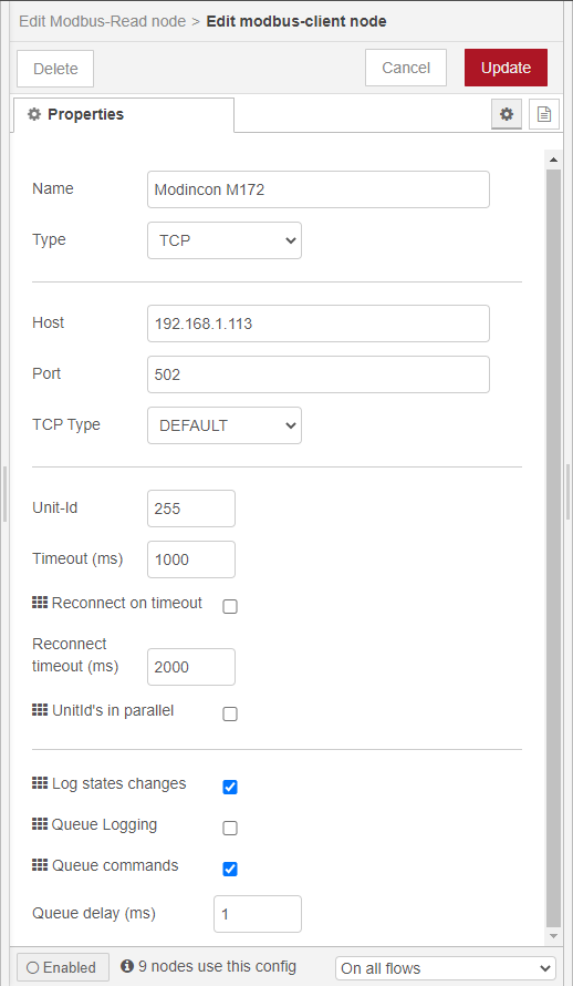
I have successfully built the project for PLC and it works, but I can't read this that through the modbus and display them. The project was built in Ecostruxure SOMachine HVAC.
When I am trying to connect to my PLC I displays and error that says "sequential dequeue command not possible".
Could someone help me to solve this ?
I will leave some screenshots with the settings.
Thank you in advance for any help.
I'll provide more info if anyone needs it.
P.S. Used PLC - Modicon TM172PDG18R
P.S.S. When I write address 8960 it retrieving me this response but I don't really know what kind of data are this.
23.06.2020, 03:51:43[node: c072310d.48e5b](http://192.168.1.104:1880/#)msg.payload : Object

object

data: array[4]

0: 0

1: 0

2: 220

3: 100

buffer: buffer[8][raw](http://192.168.1.104:1880/#)

0: 0x0

1: 0x0

2: 0x0

3: 0x0

4: 0x0

5: 0xdc

6: 0x0

7: 0x64
8960 is the address of a status variable, when I try for another address it displays:
 "Error: Modbus exception 2: Illegal data address (register not supported by device)"
"TypeError: Cannot read property 'status' of undefined"
I have found how to export the modbus addresses for my objects and those looks like this:
408960
408961
408962
408963
408964
But when I put them in address field it says
"RangeError: The value of "value" is out of range. It must be >= 0 and <= 65535. Received 408960"
I think that I have to format them... Could someone help me to understand what to do with this addresses ?
First, allow me to say that this is a great subject for a thesis. I’ve never done one, but it seems fitting.
Second, you picked one of the most non-standard “standard” methods of communication between devices.
Very few manufacturers follow the golden standard and sadly it is left up to the individual to figure out which addresses give the correct results.
Looking at your screenshots, it appears the node is setup correctly. The PLC matches your node configuration. The one thing that sticks out is the FC-03_1 element below your modbus driver.
I never have used the M172 PLC, but first impressions are that the driver allows you to add function codes as required to the driver. Within that function code element, I would imagine that there is some variable mapping allowing you to tie a variable to a modbus address.
Also, what is the offset required for the address?
Normally it is 40001 for holding registers but check the manual for the PLC.
Also, those addresses you posted look one digit too long. Verify you have the correct address and take a screenshot of the FC-03_1 configuration.
Thank you for your response !
I have remove the node from SoMachine that is related to Ethernet -> Generic Modbus because I didn't find any sense in this.
I didn't find the required offset in manual 
Here is all the guides/manual for this device. Maybe you will to find the offset that I didn't find: https://www.se.com/ww/en/product/TM172PDG18R/modicon-m172-performance-display-18-i-os%2C-ethernet%2C-modbus/
I have found that address = address - offest, so if the address 8960, I should read 8959 but the problem is that it's reading right only the EEPROM Parameters like Delta and Setpoint.
When I am trying to read analog input values that are declared as Status Variables it displays the default values of this.