If you are steadfast of heart and absolutely certain your grounds are truly common @dynamicdave circuits would work to transfer signals to pi. And you are sure the voltages are at the same level as well. Still, opto isolators are your friend even though they do take up real estate. Are you good with the code for the pin inputs? @Colin is one real good resource for code if needed
LOL, I'm not good with any of this!  I post here and scrounge the 'net for help/answers. I'm gonna use optos since I bought a tube full for a couple bucks and have plenty. Once this gets "paper built", I'm gonna try and do a pcb. I did one years ago when Rat Shack was still around and it came out pretty good. I think the rapid prototypers are out of my $$$...
Russ
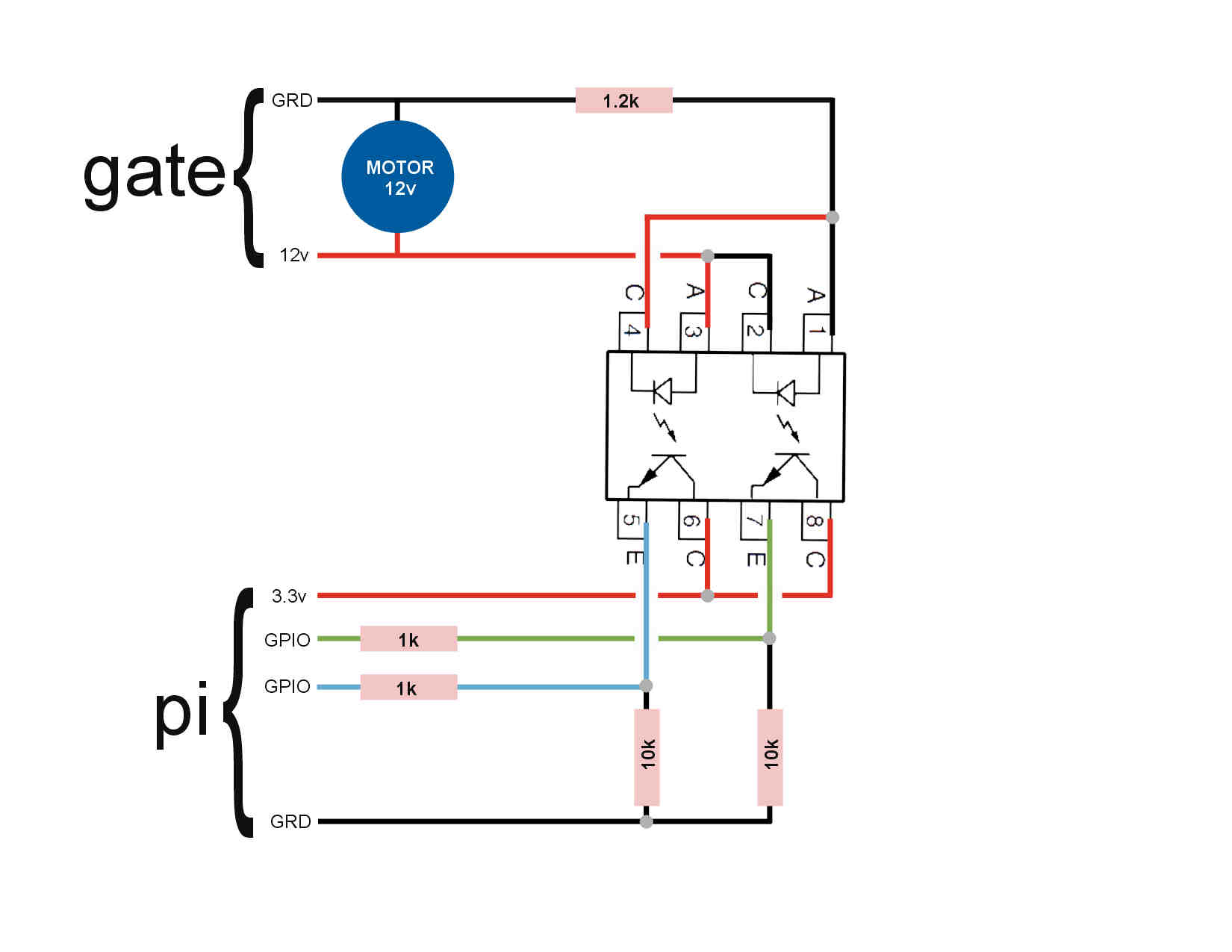
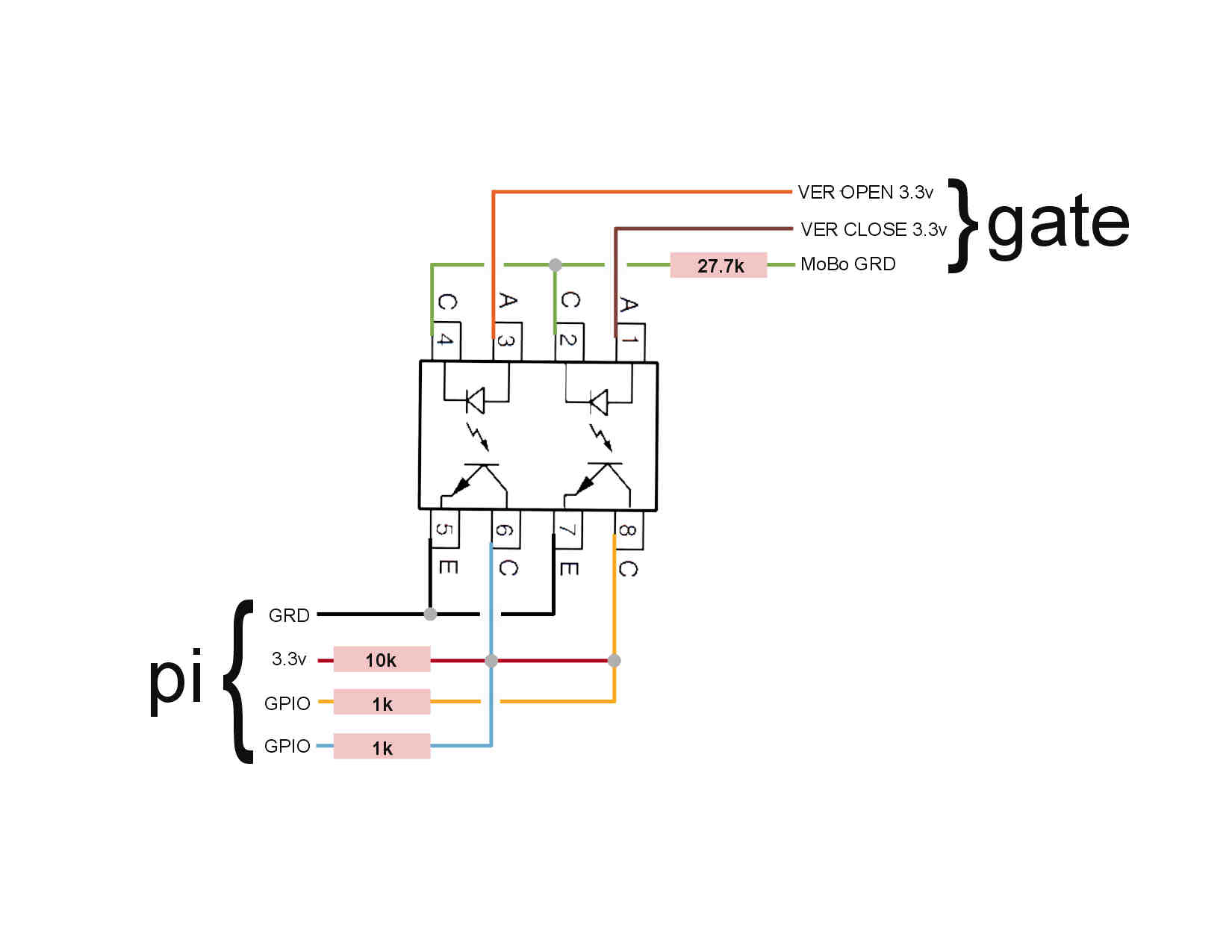
OK! For critique, here are my drawings of the verification (limit) switch inputs and the motor running inputs which will show either opening or closing depending on it's polarity. Not sure if these are "best practices" as I mostly got "internet" help by looking at others' projects. Feel free to tell me if they need work.
That leaves me with just figuring a method to short the two gate mobo contacts required to start a cycle. Mfg'er recommends a standard doorbell switch if that helps. I've tried putting a VOM on it but it's only active for maybe 50ms, to short to catch anything. I know it's making a circuit, just don't know what...
I've been using two sets of two inject nodes to send "1s" to simulate the motor running (each direction) and "0s" to stop it, which works fine. For each pair of injects, will a single GPIO pin going high & low do the same as these two injects?
Russ
**
**