Understanding and parsing 16-bit words via Modbus

I have connected an Alley Bradley PowerFlex 525 variable frequency drive to a Pi using RS485 (DSI) protocol. I can instantly get the "easy" parameters, such as:

output frequency (address: 001):

result (~58.2 Hz)

I can do the above for pretty much all the other parameters.

However, in this application, we command the motor to rotate forward and reverse for periods of time. This looks to be available (p. 193 of the manual):


(I confirmed that C122 is set to velocity)

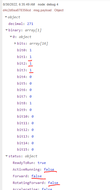
Per the above paragraph about Reading (03) Logic Status Data, since 2100 hex = 8448 decimal, I put address 8448 into the Flex Getter Modbus node and get this:

Can someone explain what I am looking at (specifically the 271 and the 1 & 15 in the buffer), and how it ties (or does not tie) with the grid / table above explaining each of the 16 logic bits? I am 90% certain this will be resolved via the Buffer-Parser node, but I would like to understand better what I am looking at before passing the contents to the B-P node.

I am attaching the flow here, although it's quite simple at this point.

[{"id":"e9a3977f5e0d61e4","type":"inject","z":"099a91da4f256498","name":"","props":[{"p":"payload"},{"p":"topic","vt":"str"}],"repeat":"10","crontab":"","once":false,"onceDelay":0.1,"topic":"","payload":"","payloadType":"date","x":770,"y":660,"wires":[["72fd6247261cfe08"]]},{"id":"72fd6247261cfe08","type":"function","z":"099a91da4f256498","name":"function 1","func":"msg.payload = {\n    value: msg.payload,\n    'fc': 3,\n    'unitid': 1,\n    'address': 8448,\n    'quantity': 1\n}\n\nreturn msg","outputs":1,"noerr":0,"initialize":"","finalize":"","libs":[],"x":860,"y":720,"wires":[["d4c2d0aa878356cd"]]},{"id":"d4c2d0aa878356cd","type":"modbus-flex-getter","z":"099a91da4f256498","name":"","showStatusActivities":false,"showErrors":true,"logIOActivities":false,"server":"a536fdaba00fed1f","useIOFile":false,"ioFile":"","useIOForPayload":false,"emptyMsgOnFail":false,"keepMsgProperties":false,"x":990,"y":780,"wires":[["48ce98bc53ee3ebc"],[]]},{"id":"48ce98bc53ee3ebc","type":"debug","z":"099a91da4f256498","name":"debug 2","active":false,"tosidebar":true,"console":false,"tostatus":false,"complete":"true","targetType":"full","statusVal":"","statusType":"auto","x":1100,"y":900,"wires":[]},{"id":"a536fdaba00fed1f","type":"modbus-client","name":"","clienttype":"serial","bufferCommands":true,"stateLogEnabled":false,"queueLogEnabled":false,"failureLogEnabled":true,"tcpHost":"127.0.0.1","tcpPort":"502","tcpType":"DEFAULT","serialPort":"/dev/ttyUSB0","serialType":"RTU","serialBaudrate":"9600","serialDatabits":"8","serialStopbits":"1","serialParity":"even","serialConnectionDelay":"1000","serialAsciiResponseStartDelimiter":"0x3A","unit_id":"","commandDelay":2000,"clientTimeout":10000,"reconnectOnTimeout":true,"reconnectTimeout":5000,"parallelUnitIdsAllowed":false}]

EDIT: After ~15 minutes, I noticed a few error messages and a change in the output from 271 to 303. Still not making any sense to me, though.

Hi Grant,

271 and 303 are the decimal representations of the Modbus data
while for 271 (decimal) its buffer in hexadecimal is 0x1 (1st byte) and 0xf (2nd byte) of the 16bit (1 x modbus register you are reading)

For the data to make sense, based on the documentation you have shared, this Buffer modbus data need to be translated to binary which represent each of the states shown in the table.

Since we dont have your device im sharing a flow that uses buffer-maker, to reverse the process and create a Buffer from the decimal values to simulate your data coming from the device and then using buffer-parser convert it to binary.

[{"id":"58ac966d042d3316","type":"inject","z":"54efb553244c241f","name":"","props":[{"p":"payload"},{"p":"topic","vt":"str"}],"repeat":"","crontab":"","once":false,"onceDelay":0.1,"topic":"","payload":"271","payloadType":"num","x":210,"y":1600,"wires":[["08987b674403c309"]]},{"id":"6136282e5f1afdf4","type":"debug","z":"54efb553244c241f","name":"debug 23","active":true,"tosidebar":true,"console":false,"tostatus":false,"complete":"false","statusVal":"","statusType":"auto","x":860,"y":1640,"wires":[]},{"id":"08987b674403c309","type":"buffer-maker","z":"54efb553244c241f","name":"","specification":"spec","specificationType":"ui","items":[{"name":"item1","type":"uint16be","length":1,"dataType":"msg","data":"payload"}],"swap1":"","swap2":"","swap3":"","swap1Type":"swap","swap2Type":"swap","swap3Type":"swap","msgProperty":"payload","msgPropertyType":"str","x":410,"y":1640,"wires":[["d331af2c32f60b2a","46162558616eca58"]]},{"id":"526f4c0ba1b974ae","type":"inject","z":"54efb553244c241f","name":"","props":[{"p":"payload"},{"p":"topic","vt":"str"}],"repeat":"","crontab":"","once":false,"onceDelay":0.1,"topic":"","payload":"303","payloadType":"num","x":210,"y":1680,"wires":[["08987b674403c309"]]},{"id":"d331af2c32f60b2a","type":"buffer-parser","z":"54efb553244c241f","name":"","data":"payload","dataType":"msg","specification":"spec","specificationType":"ui","items":[{"type":"int16be","name":"decimal","offset":0,"length":1,"offsetbit":0,"scale":"1","mask":""},{"type":"16bitbe","name":"binary","offset":0,"length":1,"offsetbit":0,"scale":"1","mask":""}],"swap1":"","swap2":"","swap3":"","swap1Type":"swap","swap2Type":"swap","swap3Type":"swap","msgProperty":"payload","msgPropertyType":"str","resultType":"keyvalue","resultTypeType":"return","multipleResult":false,"fanOutMultipleResult":false,"setTopic":true,"outputs":1,"x":650,"y":1640,"wires":[["6136282e5f1afdf4"]]},{"id":"46162558616eca58","type":"debug","z":"54efb553244c241f","name":"debug 24","active":true,"tosidebar":true,"console":false,"tostatus":false,"complete":"false","statusVal":"","statusType":"auto","x":550,"y":1560,"wires":[]}]

For 271 in binary we get

image

So according to the manual table that's

Ready to Run (bit0), Active Running (bit1), Forward (bit2), Rotating Forward (bit3) .. etc

Regarding the errors .. could be some problem with the communication especially with that cyclic redundancy check (CRC) error .. could be due to cabling or magnetic interference (modbus cables crossing high current lines) or the end of the lines not being terminated (120 ohm resistors if the devices dont already have internal termination)

Hi Grant,
if you are interested in a deeper understanding of what the buffer-parser node would do for you in this situation, you can try to replicate its functionalities with nodejs buffers:
https://nodejs.org/api/buffer.html
Basically you just need to pass the 2nd output (buffer) of the Modbus Flex Getter to a function node where you write some lines of code depending of what datatype you are trying to read:

let buf = msg.payload.buffer;

buf = buf.swap16();
msg.payload = buf.readUInt32LE(0, 4);

return msg;

Thank you @UnborN and @MountainKing91. Very helpful explanations.

@UnborN: Yes, the 120Ω resistors are not currently in place, but I will put them back in today. I took them out when I created my own cable (as shown here, where they use the wires corresponding to pins 4 & 5 from a standard Ethernet cable). I presume I need the resistors at both ends (not sure how it will fit on the end that connects to drive, but I will manage). And I will tidy up the cabling to reduce noise, interference, etc.

Andy's method worked perfectly...

However, via the other method, when using a function handling the 2nd output (buffer), I get this error:

"RangeError [ERR_BUFFER_OUT_OF_BOUNDS]: Attempt to access memory outside buffer bounds"

I tried some variations and looked up this error, but no luck.

Thank you both again for this explanation. It will help me on my next Modbus project.

There is no need to use buffer maker as the data from the flex getter contains a buffer (use a debug node set to show complete message)

Also, you can make a better output using the (arguably bad) syntax object=>property e.g...

1 Like

Thank @Steve-Mcl . Very helpful screenshot as always, but just one question.

The complete message from the 2nd output of the Modbus Flex-Getter node is as follows:

d4c2d0aa878356cd : msg : Object
object
topic: "d4c2d0aa878356cd"
messageId: "630de2446965afbffb1b13a5"
payload: object
data: array[1]
0: 271
buffer: buffer[2]
0: 0x1
1: 0xf
queueLengthByUnitId: object
unitId: 1
queueLength: 1
queueUnitId: 1
unitId: 1
modbusRequest: object
value: 1661854276004
unitid: 1
fc: 3
address: 8448
quantity: 1
emptyMsgOnFail: false
keepMsgProperties: false
messageId: "630de2446965afbffb1b13a5"
values: array[1]
0: 271
_msgid: "be351c1528b359b0"

I am trying to pass msg.payload.buffer into the Parser node that you outlined, correct?
image

image

correct - that is the buffer to pass in.

The binary output is 271 because you (and me) chose int16 (be) instead of 16bit

PS: the object syntax is => not ==>

Yep, I caught that too just after I posted. I cleaned up my object syntax, but I am still not getting the correct status output.

That is due to byte ordering (endianess).

Look at the buffer - byte 0 contains 0x1 and byte 1 contains 0xf

In the screenshot, ready to run, running etc are obtained from byte 0. byte 0 contains 0x1 or in binary 0000 0001 - so bit 0 is true, bits 1~7 are false
If you change the offset for the status=>xxxx entries in buffer parser to 1 you will get the values you are mentioning.

Thanks Steve. That did it.

Just wanted to share this. It's so refreshing to get this valuable information charted. It's still not done, but it's a good start. Really appreciate the help from everyone!

3 Likes

This topic was automatically closed 14 days after the last reply. New replies are no longer allowed.