A firefighter training flow for timed competitions with ultrasonic depth sensors and event logging

Hello all,

Hopefully this works and formats properly. This is my first Node-Red project and I know it's rather large but if anyone feels like taking a look at it and providing constructive feedback I'd appreciate it. I can't really show just one piece of the project because it all works together so I don't think pieces would make sense.

If I should have shared this differently please let me know.

I started playing around with Node-Red in an attempt to make a training prop for my local fire department that would stop a timer when a bucket was filled to a certain level. It started with a Pi Zero with a float switch and a couple of LEDs and as I ran into various issues and thought of two new things to add for every one I managed to successfully implement it morphed into this.

I had to deal with a couple of obstacles where I'm still not completely satisfied with my solutions. I had to come up with a way to make sure the date and time are correct once I decided to add a logging capability but the UI control doesn't work quite like I want to if a 2nd user connects, or the first user disconnects and reconnects, so I'm still trying to figure that out but overall I'm mostly looking for any suggestions on ways to simplify or make the program more efficient.

I ended up having to learn some Javascript when I ran into some limitations I coundn't work around with nodes, and once I knew a little I couldn't help experimenting by replacing sets of nodes with function nodes to see if I could duplicate the logic, so I know there is some logic in function nodes where the basic nodes would and did do what I needed just fine.

Thanks to everyone who contibutes to Node-Red so I can mess around with this kind of stuff in my spare time!

Edited to add: This project is running on a Pi 3 B+ with Node-Red 0.20.5 and Node.JS 10.15.3
The Rasbian image is based on Patrick Murrays ControlPi from GitLab.

Edited again to add some photos

20190529 Training Tool.json (79.1 KB)

Here is the flow that handles the start, water level tracking, and event timing for Prop 1. This is mirrored on another flow for prop 2.

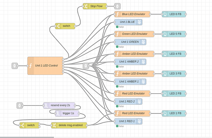
Here is the logic for the LEDs and their virtual counterparts on the UI.

Here is the Keypad to limit access to the "Tech Page" in the UI. This took me quite a while and rather pleased with the result although I'm sure I'm more proud of it now than I will be in a few years when I have more experience lol.

Here is the main page of the UI where data can be entered and the props run separately or timed against each other.

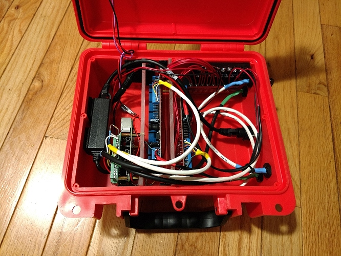
And here are a couple of photos of my hardware assembly. Everything except the Pi came from either Amazon or my scrap pile. :slight_smile: This box works quite well as a waterproof case to protect the electronics during a session. It does get a bit warm inside sitting out on the apron in the sun and I have a shutdown built into the flow if the CPU temp gets too high, but that hasn't happened yet. We try to keep it shaded which helps.

1 Like

What a great project! Well done and thanks for sharing. Also, welcome to the creative hobby of building things with Node-RED. :smile:

With large flows, it can be a good idea to share screen-shots at least of the key parts of your flow. That way, people don't have to load the flow to see what is going on.

As you have discovered, Dashboard isn't as well suited to multi-user environments. This kind of realisation is common for frameworks that provide lots of early help and support as Dashboard does. You may find that you reach a point where you are fighting with the framework rather than it supporting you. At that point, you have to make a decision whether you carry on in the same way or switch to a different tool. Of course, that would mean redoing some things. In your case, if Dashboard is getting in the way, you may need to start thinking about whether you need to switch to something like uibuilder which would give you full control over your front-end - but at the cost of you having to build that front-end yourself. While this isn't actually as bad as you may think, it is still daunting if you haven't built any web apps before as you need to know a little HTML and some JavaScript.

Anyway, cool project.

Thanks,

I tried to get some relevant screenshots that show some of what I'm doing. I keep my nodes rather spread out so I can visualize the path but I tried to capture a couple of blocks.

I don't really want multiple users, but I'm trying to make this easy for anyone to use and I know sooner or later someone else is going to log in just because they can. I am usually running one of the engines during a training exercise and one of the line officers will be using their phone to handle this part.

I learned early on that I could get by knowing the program idiosyncrasies but when someone unfamiliar tried to use it, it ended rather badly. I spent a lot of time working through those bugs though and it goes fairly well now. I like the idea of learning some more and being able to build a UI that looks the way I want it to, but this project has already taken far more of my time than I anticipated and I need to focus on more important things in my life before tackling another skill. Someday though!

2 Likes

@kocherjj That is marvelous! And the build is very impressive. I see the power supply and external jack (nice!), DHT22 and Pi in the photo and what looks like two relay boards
Couple questions
(1) it looks like you have a hat on the pi. Which one and what is it for?
(2) the relay board look like there are a log of relays - I assume they are controlling the two relays - one set for each firefighter. Are the rest for future expansion?
(30 for the timing have you thought of adding a Real Time Clock (RTC) to the pi? (https://www.adafruit.com/product/3295)

A very professional build and I wish I had a tenth of you building skill!

Thanks,

1: The Pi Hat is just a screw terminal breakout for the GPIO header. I didn't trust the jumper wires to stay put. Every connection is either soldered or landed on a screw terminal. I want this to be able to get tossed around without falling apart or having intermittent issues.

2: There are two 8 relay boards. Each prop uses 6 of them to drive the LEDs. In the 2nd screen-grab you can see the flow for controlling these. When the timer is started the lowest LED starts flashing. That is the set of triggers you can see there. There's probably a better way to do that but it works and hasn't given me any trouble. The water level percentage is fed into the LED Control Function node and the LEDs triggered as it rises. The same signal that triggers the Blue LED also stops the time, returns the result on the UI page, and logs the Date, Time, Event Name, Firefighter Name and Event Time to a log file. I have the Pi running Read Only so it sets the system to RW, writes to the log file, and then sets it back to RO again. The Emulators feed the two vertical rows of buttons visible on the UI photo. These mirror the actual LEDs so the officer can see the progress even if they can't see the prop itself at the time.

3: I didn't know those RTCs existed for the Pi. Looks like a great option and that will simplify the UI a lot. Thanks!

To further explain what is going on, the waterproof network jack is fed from a PoE+ injector that I connect to the AC generator on the Engine. There are two 7 pin and two 4 pin waterproof connectors also installed, a 7 pin for the relays and a 4 pin for the HC-SR04 on each prop.

I have a PoE+ splitter in the box that breaks out 12 Volts. That runs the relays and the LEDs and I have a 12v to 5v buck convertor soldered to the Pi Power Pads which runs the Pi and the depth sensors.

I used Red, Amber, Green and Blue Trailer Clearance Light style LEDs mounted on a board in front of the welded up target. The HC-SR04 is mounted in a 2" PVC threaded cap that goes at the top of a vertical 2" PVC pipe that goes to the bottom of the water reservoir with flow slots cut in the bottom and air bleed holes drilled into the top. the water overflows the reservoir about 16" below the sensor so it can't get wet during usage.

The whole thing draws 1.7 Amps with all LEDs lit.

I'm messing around with a simpler project now that I think should be pretty easy. I have an old dumpster rescued rack mounted power strip and I'm using another relay strip and a Pi Zero to make network controlled outlets. I have the physical setup working now but I still have to get everything installed nicely and figure out the best Low Voltage power solution.

2 Likes

You sir should get the project of the year award! What an excellent build. I'll bet there are other fire departments that would love something like this. As a matter of fact, I think I will tell my nephew - who is a fire captain in D.C. aoutthis!

Good job! And I hope your bosses appreciate you.

Here is a photo from this morning of the system setup. I snapped this between evolutions.

In case it isn't obvious, the unit on the left is "Rev 2". I learned a few lessons regarding metal cutting and welding too through this process.

Has anyone taken a look at the flow and has anything to offer regarding improvements or other beneficial changes?