FR: Wire Tie Downs

The objective of this idea is to have a little more control over how wires are visually router so that they can be arranged a little more neatly.

Like adding a waypoint on a Google Maps route, you could double-click a wire to add a tie-down, which would be represented as a dot. You could drag the dot anywhere and the wire would have to pass through it.

To delete the tie down, click it and press delete.

3 Likes

I'm sitting on the fence (and getting splinters).

I am not sure this is valid in Node-Red.
There aren't busses of wires going from one place to another.

And I've found when connecting nodes together NR does a pretty good job anyway.

No, it isn't prefect, but it is good.

I think that what you are wanting done could just as easily be done by moving the nodes.
And in some cases, use the link-out and link-in nodes sometimes.

1 Like

@quarfie this is something that has been discussed in different guises a few times.

The main difficulty is that wires do not have properties in the flow file format. So there's no easy way to store routing information without a significant change to the flow file.

We do have this proposal being considered for 3.0 which achieves a similar thing but in a more consistent way

3 Likes

Hi,

You can get a 'little' control over wire positioning depending on how much work you want to put into it.

You can install node-red-contrib-noop, set the Appearance to hide the label (text), and choose a 'neutral' icon to make it more correct for this purpose.

Copy / paste as many as you need - especially using the Group feature - and it can add to the visual appeal.

No-op nodes simply pass the messages along - they do not do ANY processing.

This ONLY works well for vertically-placed nodes due to the left-to-right layout of Node-RED itself. Yes, there have been MANY discussions on allowing flows to contain both horizontal and vertical connections. Personally, I think it would be cool to allow entry/exit points from nodes on the screen to be either vertical or horizontal, which would solve this for you, but not likely to happen soon / ever.

There have been several 'alternate' versions of NR created that do this but I don't think it's on 'The Plan' for core BR.

You can see this method break down on the bottom-right of the snapshot I posted; but it might be enough to help you.

Cheers,

Paul

A junction node in a tangle of wires would be a good place for the debug suggestion in this post

1 Like

Once again, a Change node with the default rule removed is just as good. There's no need to install an extra node for that.

5 Likes

Just want to propose what I think might be a way to address this...

... in case it hasn't been thought of this way before:

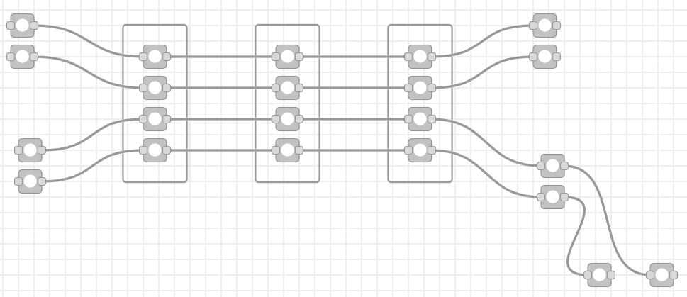
Here is an example flow:

[{
	"id": "bd5605b0fd7c0e31",
	...
	"x": 860,
	"y": 520,
	"wires": [
		["1e65d35daafa03d1"]
	]
}, {
	"id": "1e65d35daafa03d1",
	...
	"x": 1030,
	"y": 520,
	"wires": []
}]

Here it is with tie downs between these nodes:

[{
	"id": "bd5605b0fd7c0e31",
	...
	"x": 860,
	"y": 520,
	"wires": [
		["1e65d35daafa03d1"]
	],
	"ties": {
		"1e65d35daafa03d1": [
			{ "x": 900, "y": 490 },
			{ "x": 1000, "y": 490 },
		]
	}
}, {
	"id": "1e65d35daafa03d1",
	...
	"x": 1030,
	"y": 520,
	"wires": []
}]

The ties element appears in the origin node. In it you have the destination node id as a key (so you can put ties on multiple outgoing wires individually). Its value is an array of points, in order from the origin node to the destination node.

The runtime would simply ignore this data, unlike an intermediary node that it would have to iterate through. The editor presumably already reads the wires array as it's drawing the lines, and this places the ties information conveniently right next to it.

...But maybe it does clog up the flows file too much to be worth it. I don't know...

That's an interesting approach - not one I had considered. Worth thinking about alongside the junction concept I linked to.

2 Likes

You could also use a similar structure but instead of a series of x and y points, you could set a series of x or y planes. I'm thinking about a diagraming tool like Whimsical, where the lines mostly travel horizontally or vertically, and you can drag segments side to side or vertically to change the routing.

I think I would prefer that wire design, where the only curves you would see would be rounded corners and the lines are otherwise straight. I'm probably proposing something that would be way more work now... :joy:

Hi,

Of course you are correct.

The only reason I used no-op was to get the neutral gray colour I preferred. This makes it look less like an 'active component' and more like background wiring to me.

Change nodes are yellow and I don't know of an option to change the colour (maybe I missed it). I use change nodes frequently and in my mind they 'always do something'. When displayed with no label I instinctively hover over them to remind me of their function. Then I'd get the 'change: 0 rules' hover text.

As always: unbounded thanks for writing node-red! We have a team of 10 people using it daily and it replaced tools that we spent > $80,000 / year with more functionality.

Cheers,

Paul

Disclaimer: what follow is just a simple proof of concept to play around with the user interaction. It could turn into something. It could turn into nothing. There's plenty about it I like, and a few things I don't. But for a couple hours tinkering on a Saturday evening, I thought it worth sharing.

fcpLB4zj6t

27 Likes

love it :slight_smile:

Looks pretty good to me. :grinning:

At the risk of really annoying you - I don't suppose there could be an option to add a "name" to the junctions that would appear under them? Being able to annotate wires is something that would be really useful.

1 Like

Tonight's goal was to experiment with the user experience of adding junctions to the flow. It is far from a full implementation that can start considering the creeping list of features I'm sure you'll all start asking for.

4 Likes

Oh yes please :grin:

1 Like

For an evening, wow, it's pretty amazing! The main limitation I see right now is how the wires follow the same rules as nodes in terms of how they enter and exit at the left and right. So it won't work great for routing wires to the left, I think.

Haha, not taking away from your nice demo. I love it when an evenings work goes like that!

But I'll do my best not to be too creative :grinning:

1 Like

It might be problematic getting the operation right when you start moving the nodes about.

Well, since you mention it :wink:
Those new points looks like they could be attached to so for example input exit could be pinned to a new dot that would go to all debug nodes. Currently I'm using empty function node as a proxy for connection "many to many" and maintain one wire between them.
proxy

But yeah, from working PoC to final version there is always a bumpy road :slight_smile:

1 Like

I like the concept Nick. Also usfull on the i put to a node which has a lot of feeds, then you want a debug noded added to monitor what goes in.
Ticks the boxes..
1 it does nothing to flows other than amalgamate to a single wire.
2. It is small.. aka a dot big enough to see but takes little visual real estate.
It has my vote.