Driving neopixels from a CAN-Signal

node-red v3.0.2
node-red-node-pi-neopixel v2.0.0.

Hi,
this is my first experience with raspberry pi, node-red and neopixels, so please be patient with me :slight_smile:
Within my bachelor thesis i am trying to read a CAN signal and depending on the signal lighting up neopixel LED's.
The LED strip is driven by the GPIO18 of the pi and the 3,3V PWM signal is shifted to 5V by a external level shifter. The LED's are powered with a external 10Amp power supply
Reading CAN signal's and displaying them on the node-red dashboard works. I can also drive the neopixels manually via inject node.
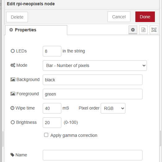
The CAN signal i need to use delivers values between 0.0 and 100.0. I want to light up the LED's depending ond the signal value. For example a value of 24 should light up the first 24 LED's of the strip.

The current flow looks like this:

I am using the following code in the function node:

'''
var canValue = msg.payload;
var maxLeds = 100;

var progress = Math.round(Math.min(Math.max(canValue, 0), 100));

var neopixelArray = ;

for (var i = 0; i < progress; i++) {
neopixelArray.push(255, 0, 0); // Beispiel für rote LEDs
}

msg.payload = neopixelArray;

return msg;
'''

Unfortunately the LED's do not light up depending on the CAN value, debugger shows the following faults:
image

Could you help me out with a proper code to drive it?
Thanks a lot :slight_smile:

Maybe it is this you are after?

[{"id":"4b38593210d42130","type":"function","z":"36262c6c92423eb2","name":"function 53","func":"let canValue = msg.payload\nlet maxLeds = 100\n\nvar progress = Math.round(Math.min(Math.max(canValue, 0), 100))\nvar neopixelArray = []\n\nfor (var i = 0; i < progress; i++) {\n    neopixelArray.push([255, 0, 0]) // Beispiel für rote LEDs\n}\n\nmsg.payload = neopixelArray\n\nreturn msg","outputs":1,"noerr":0,"initialize":"","finalize":"","libs":[],"x":430,"y":660,"wires":[["059cee6964302447"]]},{"id":"6e527c2b1820a7d4","type":"inject","z":"36262c6c92423eb2","name":"","props":[{"p":"payload"}],"repeat":"","crontab":"","once":false,"onceDelay":0.1,"topic":"","payload":"24","payloadType":"num","x":150,"y":660,"wires":[["4b38593210d42130"]]},{"id":"059cee6964302447","type":"debug","z":"36262c6c92423eb2","name":"debug 337","active":true,"tosidebar":true,"console":false,"tostatus":false,"complete":"false","statusVal":"","statusType":"auto","x":710,"y":660,"wires":[]}]

Unfortunately, the neopixel node does not accept the RGB values given by the function:
image

But the amount of RGB xxx,yyy,zzz values you see in the screenshot does match the CAN value at the beginning.
Any other idea what type of signal the neopixel node needs?
Thanks

image

neopixel node is configured like this

I would try setting a range in the msg.payload using the csv format from the node help

A range of pixels from *x* to *y* can be set by msg.payload with a CSV string *x,y,r,g,b*

[edit]Just plugged in a ring of 8 to a Pi and this node config

and this inject

lights up the first four green

1 Like

Thanks a lot, it partially works now. I am still experiencing some problems, the neopixel node often breaks down an changes its status from 'ok' to 'closed'. Debugger in front of the neopixel node shows 'Error stopping node: Close timed out' what could be the reason for this? Is the amount of messages coming from the CAN too much to handle for the neopixels? Maybe a delay node will help? For my project its absolutely adequate to transmit the signal like every 2 or 3 seconds to the pixels.

I want to display a progress bar with the neopixels, but if the progress decreases, the according pixels do not turn off again. Could that be solved with an if loop, which checks if the signal decreases?
Thanks again :slight_smile:

Use the delay node in rate limiting mode and drop intermediate messages
image

Many ways of dealing with that - a simple (but may not look good) would be to clear all the pixels on each message

1st change node saves the msg.payload and sends an all clear msg
image

Then 2nd one sends the real msg

image

Thanks for your reply, it worked so far on the test bench with CAN-signals.
I am now one step further, the LED strip is about to be implemented in the test vehicle.
Therefore I have cut the LED strip to 89 LED's which is the length i need. Before i am putting it in operation in the vehicle, i was about to test the shortened strip on the bench too.
But since i shortened it, the strip does not light up anymore unfortunately.

The testing flow to light it up testwise after shortening it looks like this:

neopixel node is configured like this:

As i mentioned i am using a Adafruit levelshifter to shift the raspberry GPIO18 signal from 3.3v to 5v.

LED's are still powered with an seperate 5v power supply.

What could be the reason for the LED's not lighting up? Does the shortening have anything to do with it?

Thanks again for your help.

When checking the data signal after the level shifter with an oscilloscope, the following results:

Can you wire up the bit you cut off and see if that works instead?

Yes, i can try that.
I guess the arrows on the strip indicate the direction of data flow?

Do you know if its possible to drive them backwards, wire up the data signal to what used to be the end of the strip originally

They are one-way devices as per arrows

in -> out

1 Like

Okay, thanks. So i wired the cut off strip to the output of the shifter, but if i turn on the power supply and start the node-red testing flow, only a few LED's light up uncontrollably... is there any way the cutting process disturbed anything? Because before that, the neopixels worked fine.
Maybe i should try another PWM-GPIO like 12, 13 or 19?

Another question: the inject node consisting of the string xx,yy,rrr,ggg,bbb.
xx indicates the number of LED's from which it should light up and yy indicates the number of illuminated LEDs, right? Does the xx-value have fixed numbers or are they always "set to zero" when they are cut off?
Thanks again for your help.

Sounds like it might have :frowning:

I've only ever used physical pin 12 for Neopixels myself

AFAIK xx = start LED, yy = end LED so theoretically if you have 89 LEDS ,then your last LED is numbered 88 but anything beyond 88 will be ignored so it makes no real difference

I don't understand your question sorry

can you show how you have this wired up please ?

It sound like you may not have a common ground between the components.

FYI It was working - they cut it shorter - it now doesn't work

The LEDs don't really have an address, but are counted from the beginning of the strip.
So it doesn't matter if you cut the strip, the first pixel is always the one with the data wire connected.

Thanks for your replies.
Let me show you how i wired it up:

As i mentioned it has worked before i cut the strip with the exact same wiring. But i have no clue how this can cause trouble to drive the LED's again as they are intended to be cut off at the defined points.

Do you have any idea where it went wrong or what causes the problem?
Thanks again.

edit: external power supply is capable of max. 10 amps at 5v output. I placed a 1000uF capacitor between ground an Vcc on the supply output

Try reducing number of pixels in the config down to 1 and see if it lights then

Get another set of neopixels (just need a few to prove your test setup isn't broken)

Bypass your level shifter (I've never needed to use one myself) The Pi 3.3V data signal has always worked for me - my current setup isn't using one. Carry on using 5V for the power

Works!
I am bypassing the shifter right now and they light up again. Seems like the shifter got in trouble at some point. Just wondering what caused it to break down...
Because I'm new to this field of electronics, I strictly followed the Adafruit Neopixel best practices guide, which strongly recommends the usage of a shifter :smiley: seems like thats not the case every time

perhaps I'll come back to you with some questions about node-red programming
Thanks again :slight_smile: